
Offset butterfly valve

a butterfly valve and valve plate technology, applied in the direction of valve details, valve arrangements, valve housings, etc., can solve the problems of impossible offset from the center of the valve plate, and achieve the effect of improving air flow efficiency

Inactive Publication Date: 2001-09-04
STERLING JAMES +1
View PDF11 Cites 14 Cited by
  • Summary
  • Abstract
  • Description
  • Claims
  • Application Information

AI Technical Summary

Benefits of technology

It is thus an object of the invention to provide an offset butterfly valve with improved air flow efficiency with no interruptions extending into the valve air flow conduit while a cross section of the conduit is essentially round and a consistent diameter for the length of the valve and the valve plate rotatably positioned and offset therein is an oblique cross section of the conduit.

Problems solved by technology

One of the problems with the offset butterfly, is that rotating a round or oblique valve plate in a cylindrical conduit about a rotational axis offset from the center of the valve plate and offset from the center of the conduit is impossible because the maximum diameter of the valve plate will not be accommodated by the dimensional cross section within the conduit along the plane parallel with the rotation axis of the valve plate and parallel with the center of the conduit.

Method used


Image

  • Offset butterfly valve
  • Offset butterfly valve
  • Offset butterfly valve

Examples


Embodiment Construction

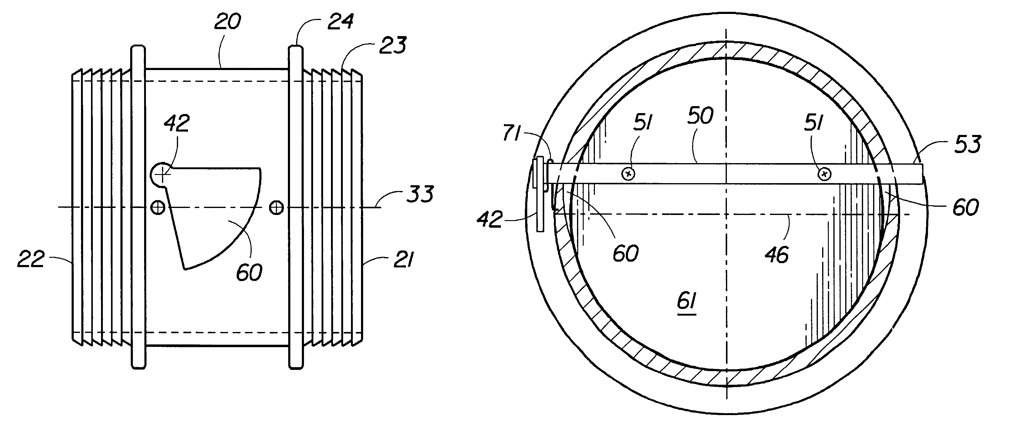
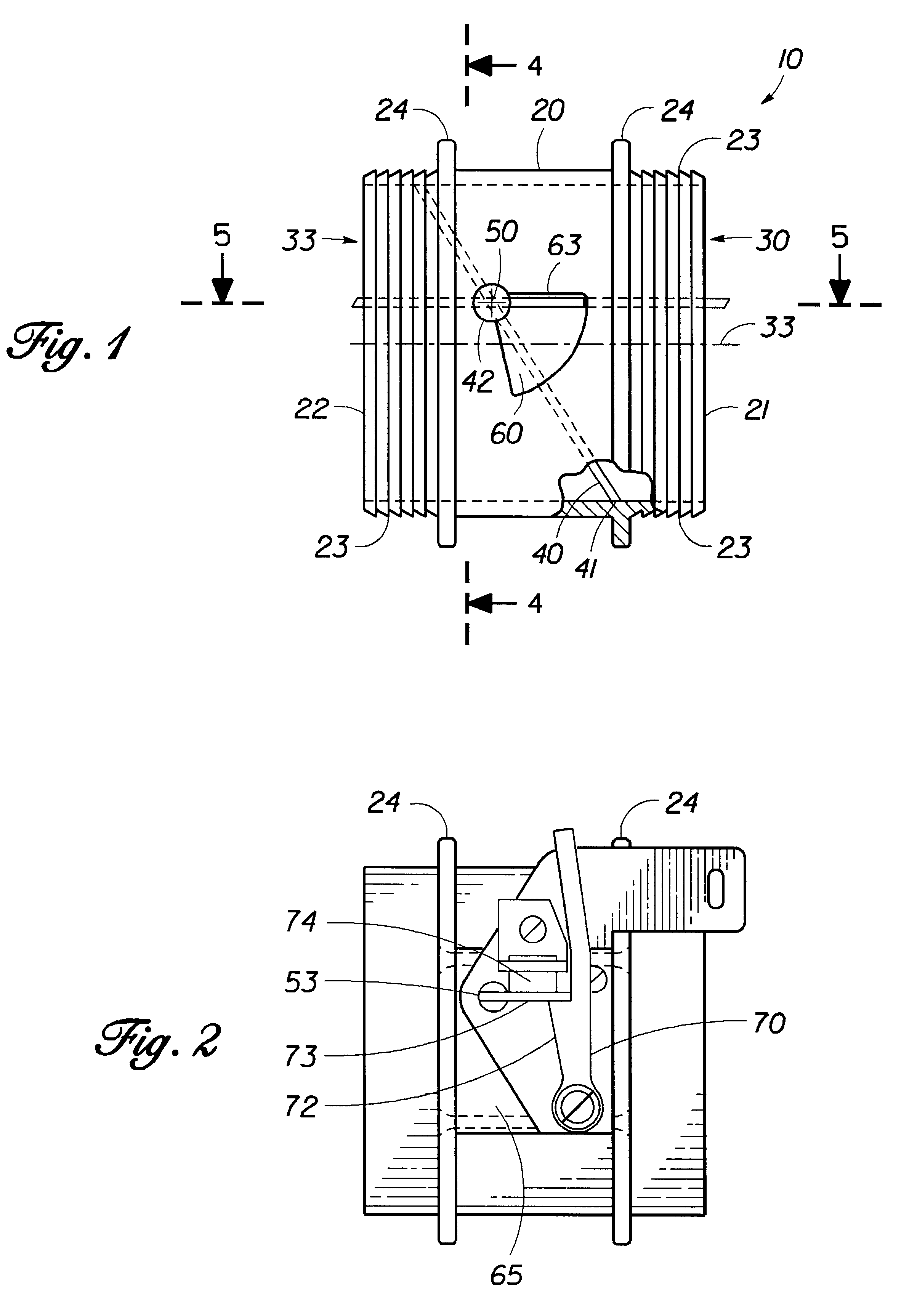
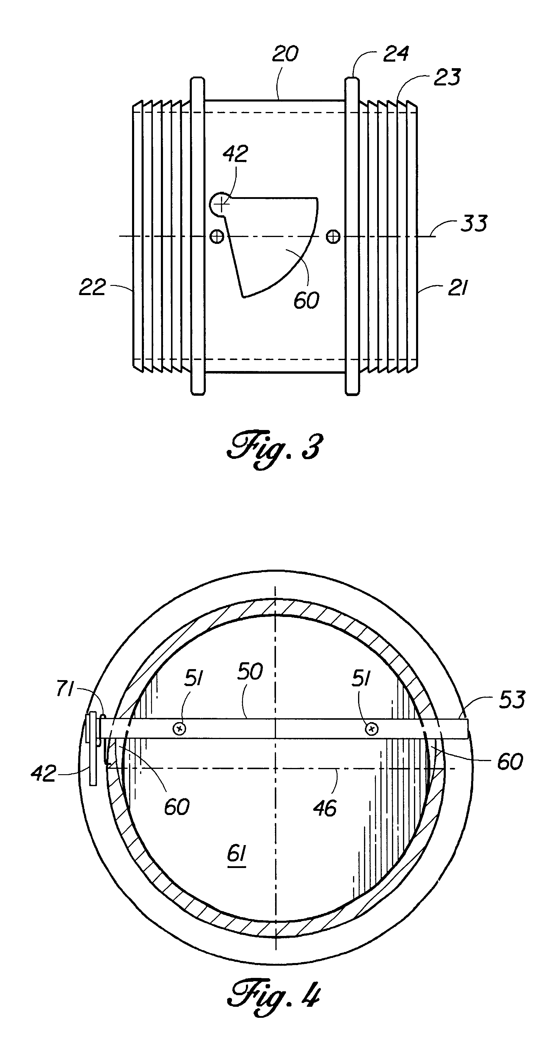
It can be seen from the following description that the present butterfly valve over comes problems associated with air flow disruption through a conduit of the valve providing an efficient easily manufactured and cost effective valve suitable for numerous applications. The butterfly valve 10 includes the main components; valve body 20, conduit 30, valve plate 40, valve plate shaft 50, two opposing indentations 60, and tripping means 70.

The valve body 20 is basically cylindrical in shape with an upstream end 21, where air enters the valve through conduit 30, and a down stream end 22 where air exits the valve through conduit 30. Depending upon the application of the valve, the upstream and down stream ends may be reversed. The valve body 20 may be constructed by numerous methods including forging, molding, turning and the like. The valve body 20 may be constructed of various materials depending on the application for the valve including stainless steel, aluminum, and plastic. Either o...


PUM


Abstract

An offset butterfly valve with a valve body, air flow conduit extending there through, and an offset rotatably mounted valve plate. The air flow conduit has with no interruptions to impede air flow there through. Cross sections along any location of the conduit are essentially round and of equal diameter while the valve plate is the shape of an oblique cross section of the conduit and rotatably mounted therein. The valve plate axis of rotation is offset with respect to the center of the valve plate and further offset with respect to a center of the conduit. Rotation of the valve plate within the conduit is accomplished by providing two opposing indentations on the interior of the conduit which accommodate the maximum diameter dimension of the valve plate when the valve plate is rotated to an open position. The indentations do not interrupt air flow through the conduit or the sealing of the valve plate periphery which may be easily machined to seal with a sealing surface of the interior of the conduit. A valve plate shaft may be contained within the valve body or may be accesses by removable side mount blocks. Various activation, biasing, or latching mechanisms may be included on the valve plate shaft and the valve may be utilized as a check or a positive shut-off valve.

Description

The present invention relates to butterfly valves and more particularly to a butterfly valve with a valve body air flow conduit there through with no interruptions to impede or disrupt air flow. Any cross section of the conduit is about equal in diameter and essentially round. A valve plate is dimensioned as an oblique cross section of the conduit at a location in the conduit where the valve plate will seal. The valve plate has first and second coplanar sections extending on respective sides of its axis of rotation while the axis of rotation is offset with respect to the center of the valve plate and offset with respect to a center of the conduit. Rotation of the offset oblique shaped valve plate within the round conduit is accomplished by two opposing indentations on the interior surface of the conduit which accommodate a maximum diameter of an opened valve plate. The peripheral edge of the valve plate is easily machined to seal with an interior surface of the conduit which is cont...

Claims


Application Information

Patent Timeline
Patent Type & Authority Patents(United States)
IPC IPC(8): F16K27/02F16K1/22
CPCF16K27/0218F16K1/22
Inventor DENTON, DANIEL WEBSTERDENTON, JEWEL MARIE
Owner STERLING JAMES
Learn More