Power supply

a power supply and power supply technology, applied in the direction of ignition automatic control, dynamo-electric converter control, instruments, etc., can solve the problems of high electricity cost, lower power cost during off-peak periods, and high cost during on-peak periods

Inactive Publication Date: 2001-09-04
BATTLLE MEMORIAL INST +1
View PDF14 Cites 114 Cited by
  • Summary
  • Abstract
  • Description
  • Claims
  • Application Information

AI Technical Summary

Problems solved by technology

The cost of delivering electricity is a strong function of demand and varies substantially during the course of the day and season.
The result is lower power cost during off-peak periods and higher cost during on-peak periods.
Therefore, the cost of power for air conditioning is expected to be substantially greater in the future than at present even though the total cost of power in aggregate may be lower.
Another effect of electric industry deregulation is possible lower reliability of grid power.
This effect, even if it does not occur, will, at a minimum, cause anxiety among customers.
When combined with already existing anxiety over power outages due to natural disasters, this is expected to cause increasing demand for standby or emergency on-site power generating capability.
However, the present approach to on-site power genration leaves much to be desired.
This becomes problematic for generators used in standby service because the generator must be sized for the worst case load.
As is readily apparent, on-site power generation tends to be expensive because of the large generator capacity needed under start-up conditions.
Further this capacity is little used since outages tend to be infrequent and of limited duration.
Such units have large start up draws and use large amounts of energy during peak peaks of electrical energy consumption.
Typically in such a situation, a large load operating off the generator is terminated when the grid goes off.
Although indiscriminate transfer can result in occasional poor performance during transfer because of the application of out of phase power sources, it has been found that it is not necessary that the grid and the generator be locked into phase for effective transfer.

Method used


Image

  • Power supply
  • Power supply
  • Power supply

Examples


Embodiment Construction

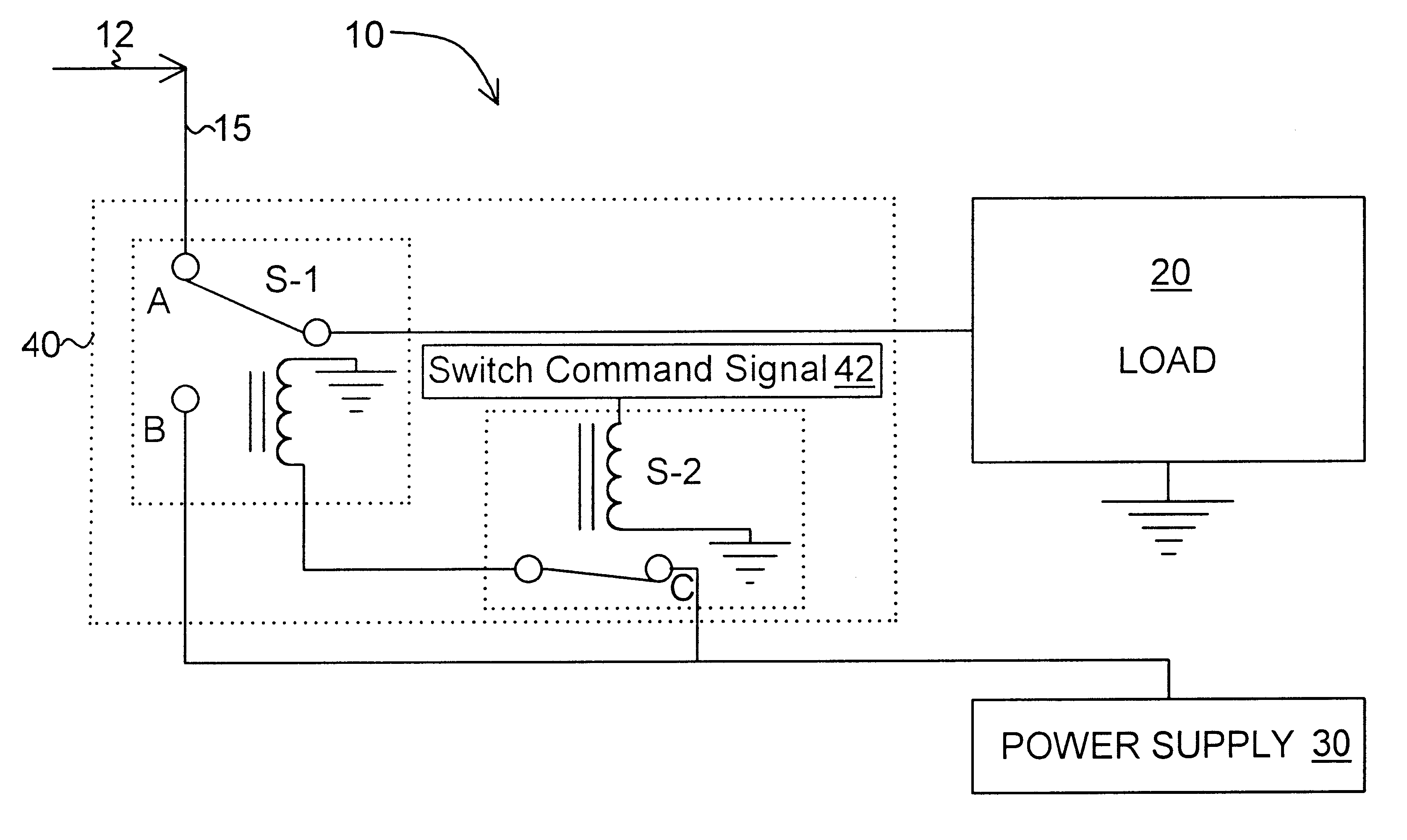
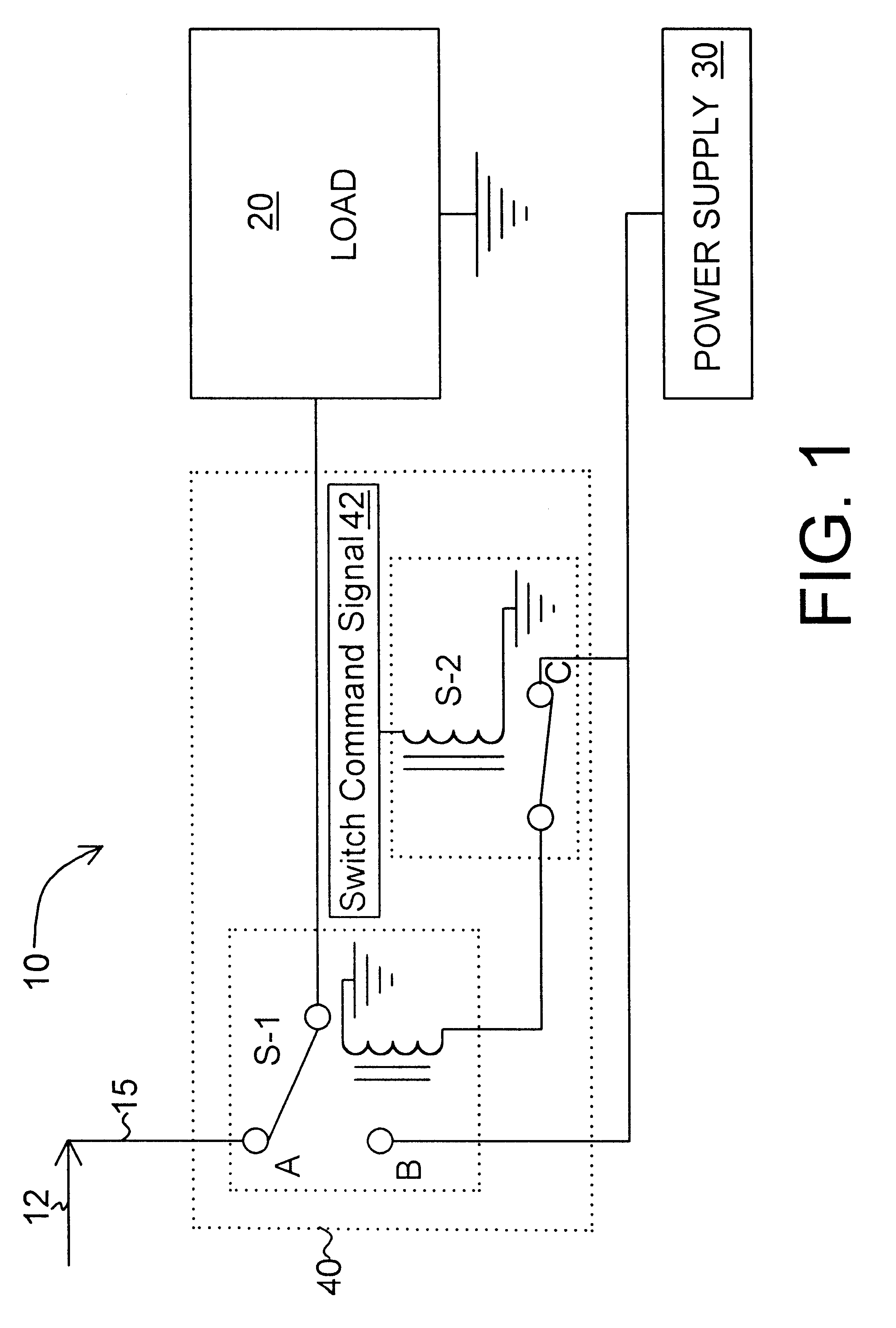
In essence and with reference to the drawings and initially FIG. 1, the power supply of the present invention is designated generally by the numeral 10 and comprises a power grid conductor 15 connected to an electrical power grid 12 (hereinafter "grid") operated by an electricity provider such as a public utility, commercial supplier, government, private distribution network, or cooperative association, a load 20, an electrical power supply 30, and a switching mechanism 40 that: 1) isolates the grid 12 from the power supply 30 at all times, 2) connects the load 20 to the power grid conductor 15 for initial start up at high power draw, and 3) connects the load 20 to the power supply 30 after the initial high power draw has been met by the grid to provide a lesser, operating power draw.

One of the unique features of this invention not available with conventional standby power supplies is that the switch mechanism 40 allows a more cost-effective power supply 30 to provide running electr...


PUM


Abstract

The present invention is a power supply (10) that starts a load (20) with a heavy start-up power draw from a power grid (12) and then switches the load to a generator (22) for lower power draw operation thereby avoiding the need for a large capacity generator capable of initial start-up of the load (20). The power supply comprises a conductor (15) for connecting to a power grid, an electrical power generation device (30), an electrical power using device or load (20) and a switching mechanism (40) for 1) isolating the power grid (12) from the power generation device (30), 2) connecting the power grid conductor (15) to the electrical power using device (20) for the initial start-up of the power using device (20), and 3) connecting the power generation device (30) to the power using device (20) after initial start-up. In addition the power supply (10) can also serve as a backup source of power for multiple circuits whose total startup load exceeds the total output of the generator (30) during periods of grid power failure by selectively turning off interruptible circuit load (20) during the startup of other circuits (16) or allowing intermittent circuit loads (20) to complete their cycle and return to an off state prior to the start-up of other circuits (16).

Description

1. Field of the InventionThis invention pertains to an electric power supply system and more particularly to an electric power supply system that includes a power grid source and an electrical power generation source (generator) with a switching mechanism that 1) electrically isolates the grid from the power generation device, 2) starts a power using device (load ) from the grid and 3) uses the power generation device for operating the load after initial startup from the grid. By using grid startup, the generator can be "undersized" to meet running rather than startup load capacity. In addition, the generator can also be used as a backup electrical supply when the power grid is down. In such instances, the "undersized" generator is fully utilized by using intelligent load control to schedule startup and operation of critical circuits.2. Background of the InventionMany changes are occurring in the electric power industry due to utility deregulation and opening of competitive markets....

Claims


Application Information

Patent Timeline
Patent Type & Authority Patents(United States)
IPC IPC(8): H02J3/00G05F1/00H02J3/38H02P1/26
CPCH02P1/26H02J3/005H02J3/007
Inventor BALL, DAVID A.HANNA, WILLIAM T.STETS, JOSEPH A.
Owner BATTLLE MEMORIAL INST
Why Eureka
Try Eureka