Ink jet head

Inactive Publication Date: 2001-09-11
CANON KK
View PDF8 Cites 38 Cited by
  • Summary
  • Abstract
  • Description
  • Claims
  • Application Information

AI Technical Summary

Problems solved by technology

Also, the increasing of density of dyes in the nozzle portion tends to higher density of prints at the start of printing, causing the unevenness thereof.
Also, it has been found that the longer the interval between the last and current discharges, the more the evaporation is advanced, presenting these drawbacks more conspicuously.
Here, however, the frequent predischarges result in the increased a

Method used


Image

  • Ink jet head
  • Ink jet head
  • Ink jet head

Examples


embodiment 1

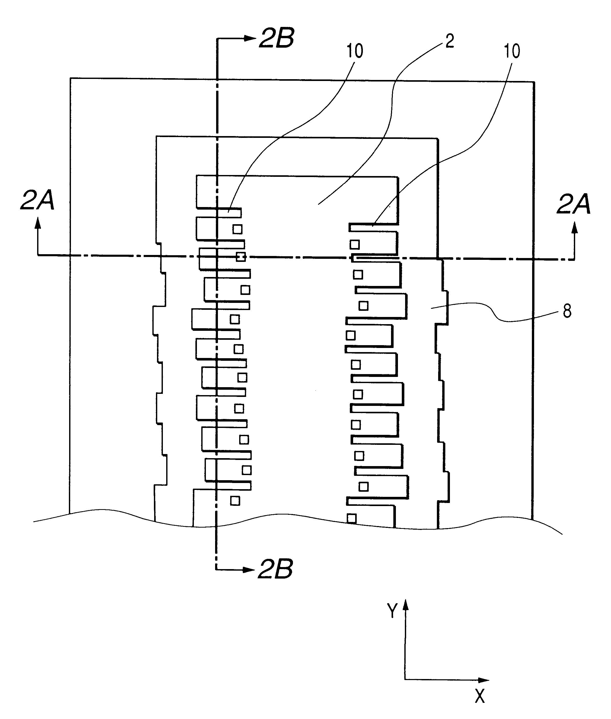
FIG. 1 is a front view which shows the arrangement of an ink jet head in accordance with a first embodiment of the present invention.

In FIG. 1, reference numeral 7 designates the elemental substrate where the electrothermal converting elements 5 are formed for discharging ink; 1, discharge ports comprising a plurality of openings arranged on the elemental substrate to discharge ink; 8, a plurality of grooves arranged on the circumference of the discharge ports; and 2, an orifice plate having the discharge ports formed therefor.

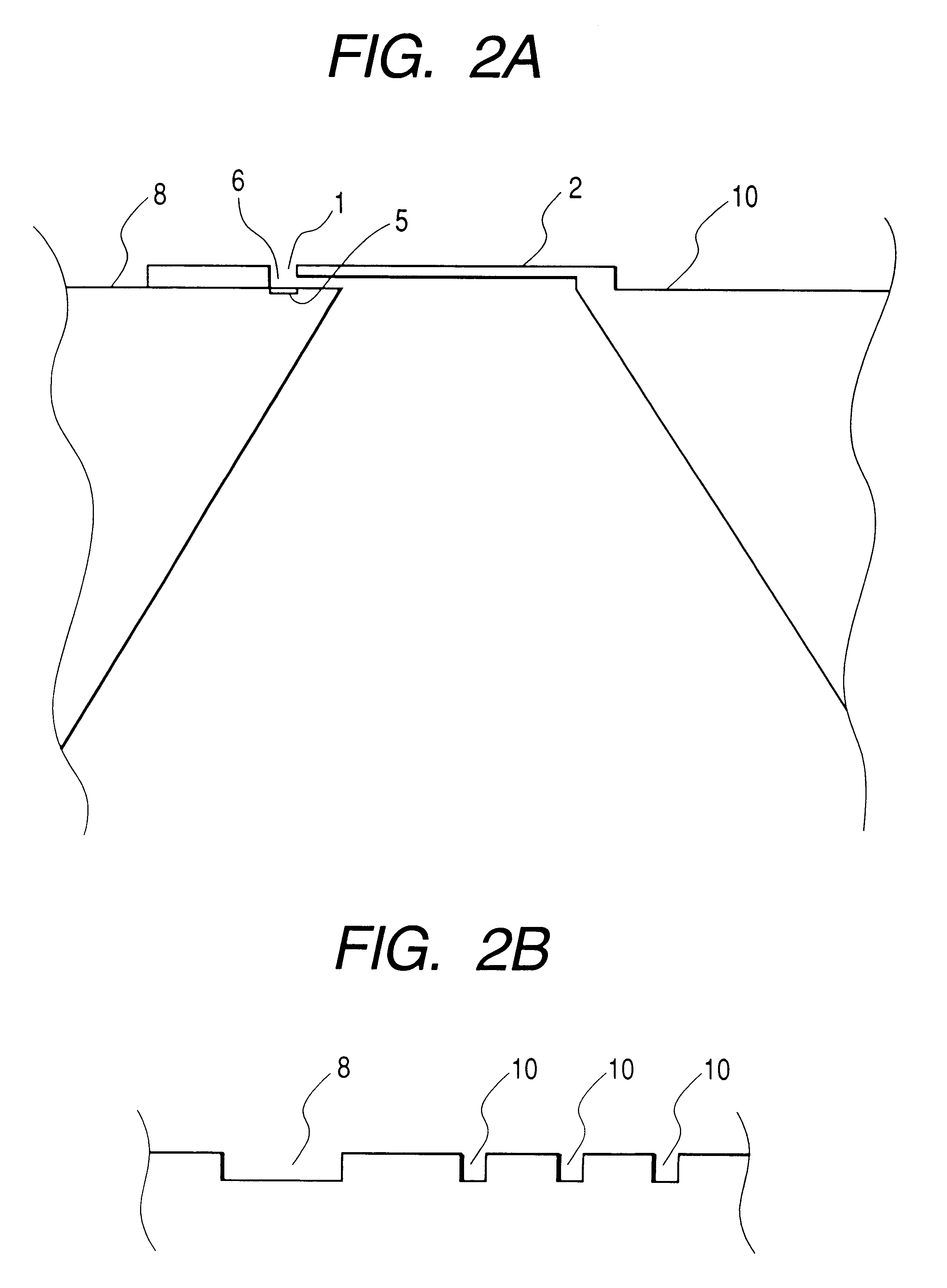
Also, FIG. 2A is a cross-sectional view which shows the section taken along line 2A--2A in FIG. 1. In FIG. 2A, reference numeral 6 designates a nozzle. Here, the groove 8 is formed perpendicular to the orifice plate. When ink is stored in the evaporation suppressing grooves 10 connected with the grooves 8, it becomes possible to suppress the evaporation of ink from the discharge port 1 nearby.

Each width of the evaporation grooves is 20 .mu.m, and each depth th...

embodiment 2

FIG. 6 is a front view which shows the arrangement of an ink jet recording head in accordance with a second embodiment of the present invention.

For the present embodiment, the resolution of the discharge ports 1 is such as to necessitate the arrangement of 150 pieces at intervals of 600 DPI per side.

Also, the size of the discharge port 1 is 12.times.12 .mu.m. The gap between the groove 8 and each of the discharge ports 1 is 50 .mu.m.

Unlike the first embodiment, the evaporation suppressing grooves 10 are arranged in the vicinity of each of the discharge ports, respectively, separated from the groove 8.

The size of each evaporation suppressing groove 10 is 10.times.25 .mu.m. In accordance with the present embodiment, the evaporation suppressing grooves are provided particularly for the discharge ports near to each of them, respectively, for the purpose of enhancing the effect of suppression against the evaporation of ink.

The evaporation suppressing grooves 10 are in the condition of ha...

embodiment 3

FIG. 8 is a front view which shows the arrangement of an ink jet recording head in accordance with a third embodiment of the present invention.

For the present embodiment, the resolution of the discharge ports is such as to necessitate the arrangement of 156 pieces at intervals of 300 DPI per side. Also, the size of the discharge port 1 is 20.times.20 .mu.m. The gap between the groove 8 and each of the discharge ports 1 is 100 .mu.m.

Ink is retained in each of the evaporation suppressing grooves 10 connected with the groove 8, thus preventing it from being evaporated from each of the discharge ports 1 nearby.

Each width of the evaporation suppressing grooves 10 is 25 .mu.m. Each depth thereof is 3 .mu.m. The distance from each of the discharge ports is approximately 20 .mu.m.

Also, each length of the evaporation suppressing grooves 10 is different to arrange it be in accordance with the deviated position of each discharge port. In other words, each of the evaporation suppressing grooves...


PUM


Abstract

An ink jet head is provided with an orifice plate having a plurality of discharge ports being open thereto. This ink jet head comprises evaporation suppressing groove in the vicinity of the discharge ports. With the arrangement thus formed, it becomes possible to heighten the humidity in the atmosphere in the vicinity of discharge ports, hence suppressing the evaporation from the discharge ports for the prevention of unstable discharges.

Description

1. Field of the InventionThe present invention relates to an ink jet recording head that forms images on a medium by enabling ink or other liquid to fly onto the medium.2. Related Background ArtFor the ink jet recording, ink or other liquid is caused to fly onto a medium for the formation of images. More specifically, it is arranged to discharge liquid from the discharge ports of an ink jet head as shown in FIG. 10. FIG. 10 is a front view which shows the recording device substrate of a side shooting type ink jet head.In FIG. 10, reference numeral 1 designates a plurality of ink discharge ports arranged on the recording substrate for discharging ink; and 2, an orifice plate. An ink supply opening 3 is open substantially in the center of the recording element substrate on which the discharge ports are arranged to supply ink to the discharge ports.This opening is usually made by means of sandblasting, anisotropic etching, laser processing, or the like.FIG. 11 is a cross-sectional view...

Claims


Application Information

Patent Timeline
IPC IPC(8): B41J2/14B41J2/05B41J2/16
CPCB41J2/1404B41J2002/14387
Inventor MURAKAMI, SHUICHIKANEKO, MINEOTACHIHARA, MASAYOSHIMIZUTANI, MICHINARIINOUE, TAKASHIAKAMA, YUICHIRO
Owner CANON KK
Why Eureka
Try Eureka