Limited angle universal joint
a limited angle, universal joint technology, applied in the field of universal joints, can solve the problems of limited angle, large device, limited angulation, and high cos
- Summary
- Abstract
- Description
- Claims
- Application Information
AI Technical Summary
Problems solved by technology
Method used
Image
Examples
Embodiment Construction
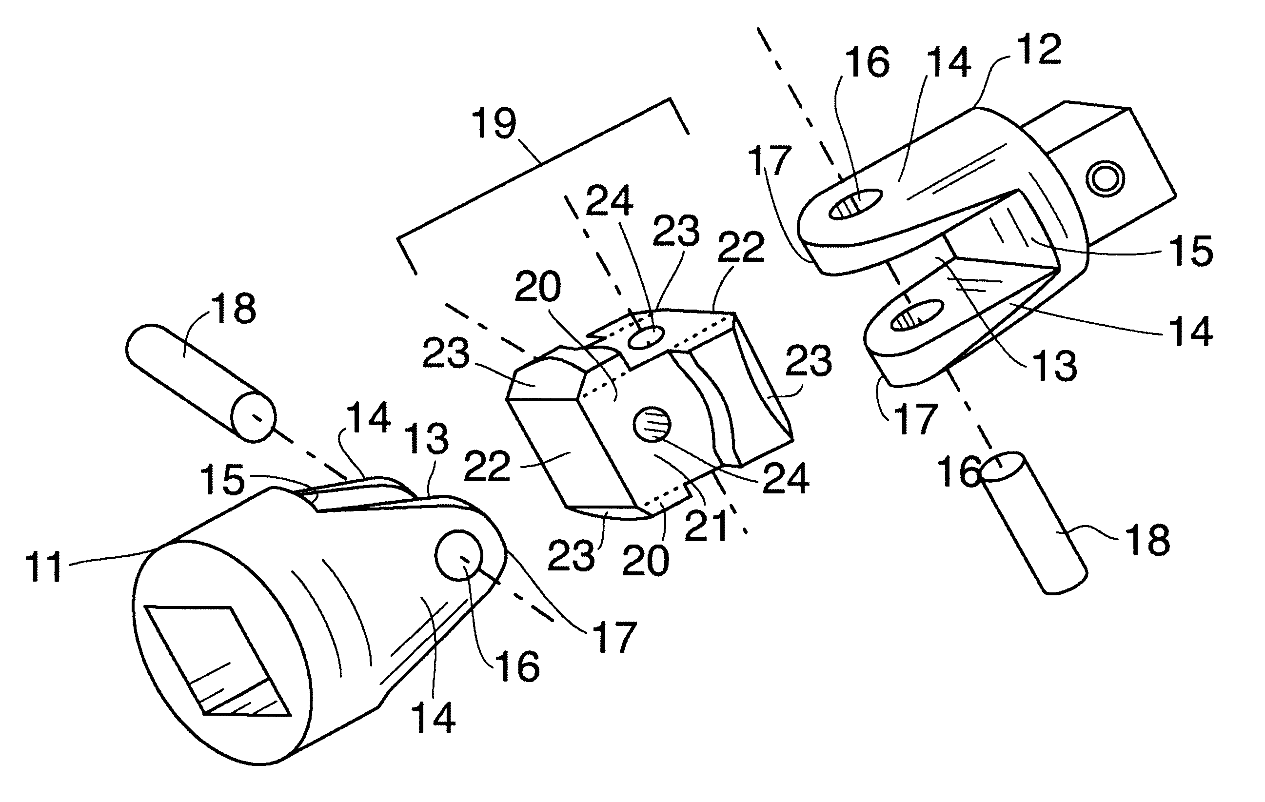
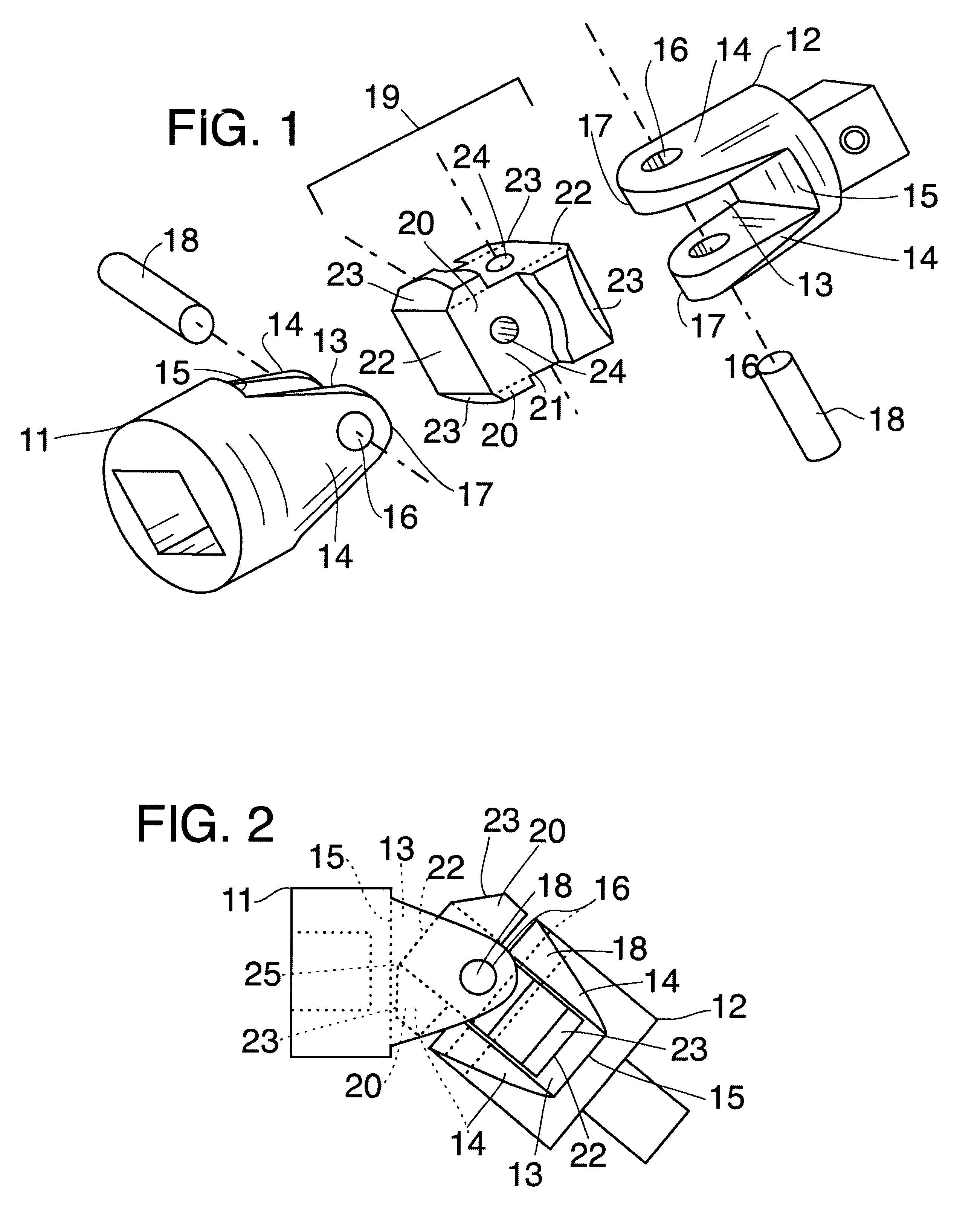
Refering to the drawings, FIGS. 1 and 2, with greater particularity, this limited angle universal joint has end sections 11 and 12, section 11 representing the female portion of this universal joint, and section 12 representing the male end although these end sections may be of any configuration desired. Each of the sections has a yoke 13 on the medial end formed by lateral walls 14, end abutment wall 15, retaining pin holes 16 in the lateral walls 14, and a rounded medial terminal end 17. Retaining pins 18 run through holes 16 and pivotal pin holes 24 of the center section. The width of the yokes on either end section are equal as are the depths.
The center, angle limiting section 19 is the shape of two T's, the top of the T's being at opposite ends and at 90 degrees to each other, each having a thickness to slip into the equal width yokes 13 and thereby creating a common center core section 21. Each "T" amounts to lateral extensions 20 off a basic square center core 21. This square...
PUM
 Abstract
Description
Claims
Application Information
 - R&D
- Intellectual Property
- Life Sciences
- Materials
- Tech Scout
- Unparalleled Data Quality
- Higher Quality Content
- 60% Fewer Hallucinations
Browse by: Latest US Patents, China's latest patents, Technical Efficacy Thesaurus, Application Domain, Technology Topic, Popular Technical Reports.
© 2025 PatSnap. All rights reserved.Legal|Privacy policy|Modern Slavery Act Transparency Statement|Sitemap|About US| Contact US: help@patsnap.com


