Embedded trimmable resistors

a technology of resistors and trimmable parts, applied in the direction of resistor details, resistor enclosure/enclosement/embedding, printed element electric connection formation, etc., can solve the problems of occupying a relatively large area for resistor creation, affecting the operation of the heart, and endangering the well-being of the person

Inactive Publication Date: 2001-09-11
INTERMEDICS
View PDF41 Cites 14 Cited by
  • Summary
  • Abstract
  • Description
  • Claims
  • Application Information

AI Technical Summary

Problems solved by technology

For a variety of reasons, a person's heart may not function properly and, thus, endanger the person's well-being.
However, the creation of resistors tends to occupy a relatively large area on the surface of the substrate.
Unfortunately, because the entire circuit must typically be complete before the deposited resistive material may be fired to form the final resistor, a resistor cannot be trimmed to the appropriate resistance level unless it is deposited at the surface.

Method used


Image

  • Embedded trimmable resistors
  • Embedded trimmable resistors
  • Embedded trimmable resistors

Examples


third embodiment

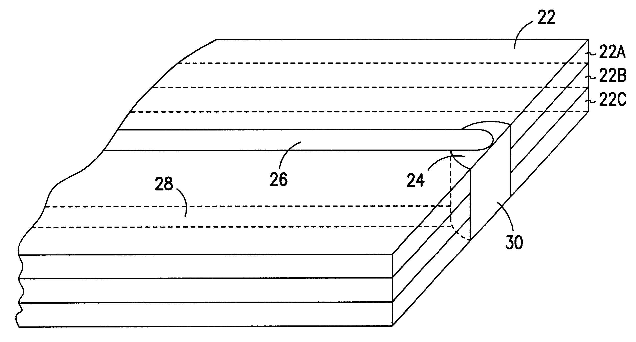
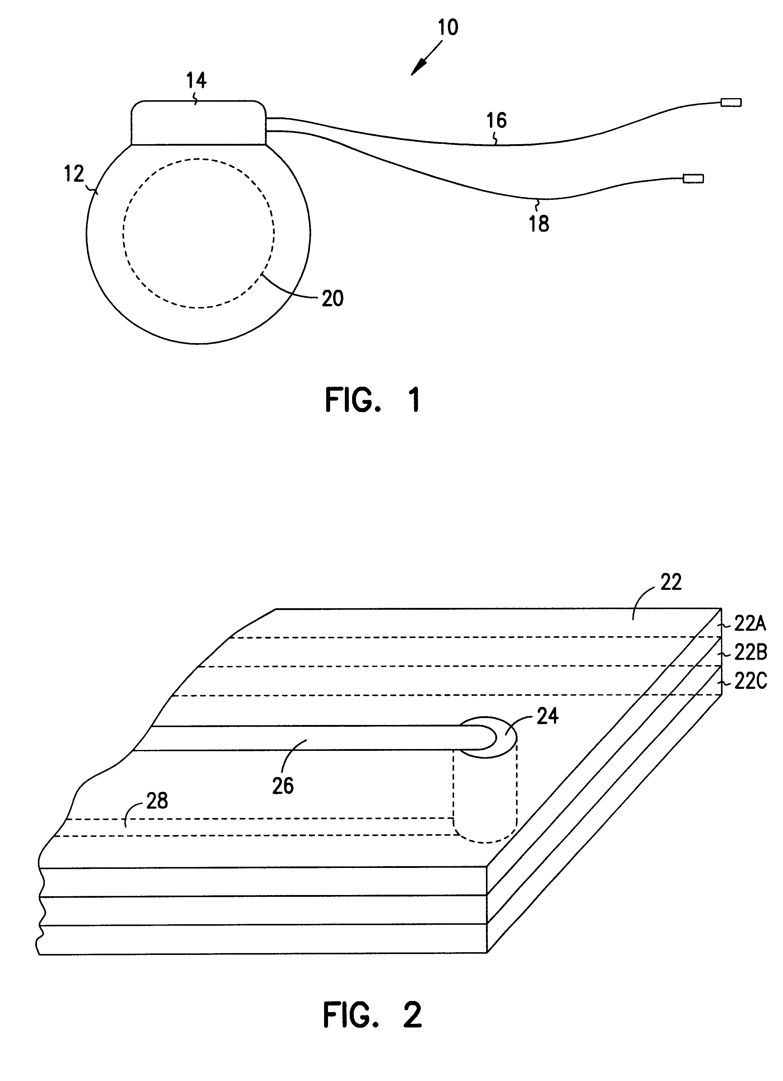
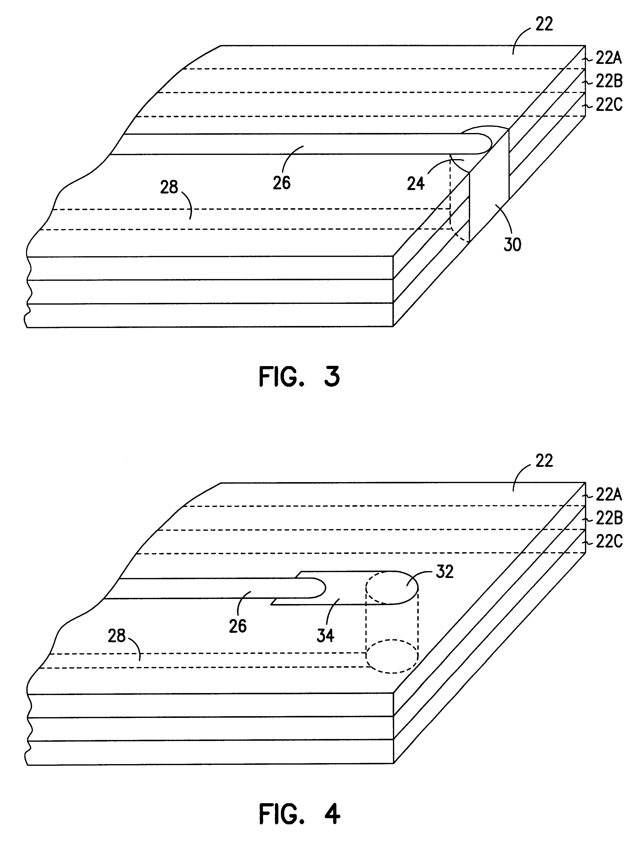
FIGS. 5 and 6 illustrate an embedded trimmable resistor. Again, for the purposes of clarity, elements similar to those discussed previously will be designated with the same reference numerals. Unlike the previously embodiments in which the resistor is illustrated as extending between an upper surface and a lower surface of the substrate 22, FIG. 5 illustrates a resistor 40 which resides in a cavity and only extends through an interior layer 22B of the substrate 22. Hence, the resistor 40 is completely covered by the layers 22A and 22C of the substrate 22. A conductor 26 may be disposed on the upper surface of the layer 22B and a conductor 28 may be disposed on the lower surface of the layer 22B to provide electrical coupling to the resistor 40. A portion 46 of the resistor 40 which extends through the layer 22B will ultimately be exposed, as illustrated in FIG. 6, so that the resistor 40 may be trimmed to the desired resistance level.

In addition to the portion of the resistor 40 tha...

fourth embodiment

an embedded trimmable resistor is illustrated in FIGS. 7 and 8. Like the resistor 40, the main portion of the resistor 50 is disposed through an interior layer 22B of the substrate 22. However, unlike the third embodiment, the conductors 26 and 28 that are coupled to the resistor 50 are disposed on the upper and lower outer surfaces, respectively, of the substrate 22. Therefore, to connect the conductors 26 and 28 to the embedded resistor 50, vias are formed in the upper layer 22A and the lower layer 22C. The vias may be filled with conductive material, or the vias may be filled with resistive material similar to the resistive material used to form the resistor 50. Like the first and third embodiments described above, the resistor 50 is advantageously fabricated near an edge of the substrate 22 so that a portion of the edge may be removed to expose a portion 52 of the resistor 50. Once exposed, the portion 52 of the resistor 50 may be trimmed to adjust the resistance of the resistor...


PUM

PropertyMeasurementUnit
electrically resistiveaaaaaaaaaa
resistanceaaaaaaaaaa
electrically conductiveaaaaaaaaaa

Abstract

A resistor may be embedded into a substrate. A portion of the resistor may be exposed, by segmenting the substrate, for instance, so that the resistor may be trimmed to a desired resistance level. Alternatively, a portion of a resistor may be embedded into a substrate, with another portion of the resistor being disposed on the outer surface of the substrate. The portion of the resistor on the outer surface may be trimmed to adjust the resistance of the resistor to a desired level.

Description

1. Field of the InventionThis invention relates generally to circuit fabrication and, more particularly, to resistor fabrication.2. Background of the Related ArtFor a variety of reasons, a person's heart may not function properly and, thus, endanger the person's well-being. Medical devices have been developed to facilitate heart function. For instance, if a person's heart does not beat properly, a cardiac stimulator may be used to provide relief. A cardiac stimulator is a medical device that delivers electrical stimulation to a patient's heart. A cardiac stimulator generally includes a pulse generator for creating electrical stimulation pulses and a conductive lead for delivering these electrical stimulation pulses to the designated portion of the heart.Cardiac stimulators generally fall into two categories, pacemakers and defibrillators, although some cardiac stimulators may perform both functions. Pacemakers supply electrical pulses to the heart to keep the heart beating at a desi...

Claims


Application Information

Patent Timeline
Patent Type & Authority Patents(United States)
IPC IPC(8): H01C17/22H01C17/242H05K1/16H05K3/00H05K3/40H05K1/09
CPCH01C17/242H05K1/167H05K1/092H05K3/0052H05K3/403H05K3/4053Y10T29/49101H05K2201/09563H05K2203/171Y10T29/49099Y10T29/49082Y10T29/49089H05K2201/0919
Inventor ULMER, KENNETH R.
Owner INTERMEDICS
Why Eureka
Try Eureka