Method for testing soil contamination, and probe therefor

a soil contamination and probe technology, applied in the direction of geological measurements, extracting sample devices, underground/near-surface gas detection, etc., can solve the problem of fluid pressure differential in the soil, local increase of the quantity of fluid near the probe tip, and contaminant fluids being prone to migrate in the soil

Inactive Publication Date: 2001-09-18
TARTRE ANDRE
View PDF14 Cites 38 Cited by
  • Summary
  • Abstract
  • Description
  • Claims
  • Application Information

AI Technical Summary

Benefits of technology

a seal mounted to said main body at said inner conduit first top opening, to prevent fluid passa

Problems solved by technology

This results in a local increase of the quantity of fluid near the probe tip, which creates fluid pressure differentials in the soil.
The contaminant fluids will consequently be prone to migrating in the soil according to fluid pressure gradients inst

Method used


Image

  • Method for testing soil contamination, and probe therefor
  • Method for testing soil contamination, and probe therefor
  • Method for testing soil contamination, and probe therefor

Examples


first embodiment

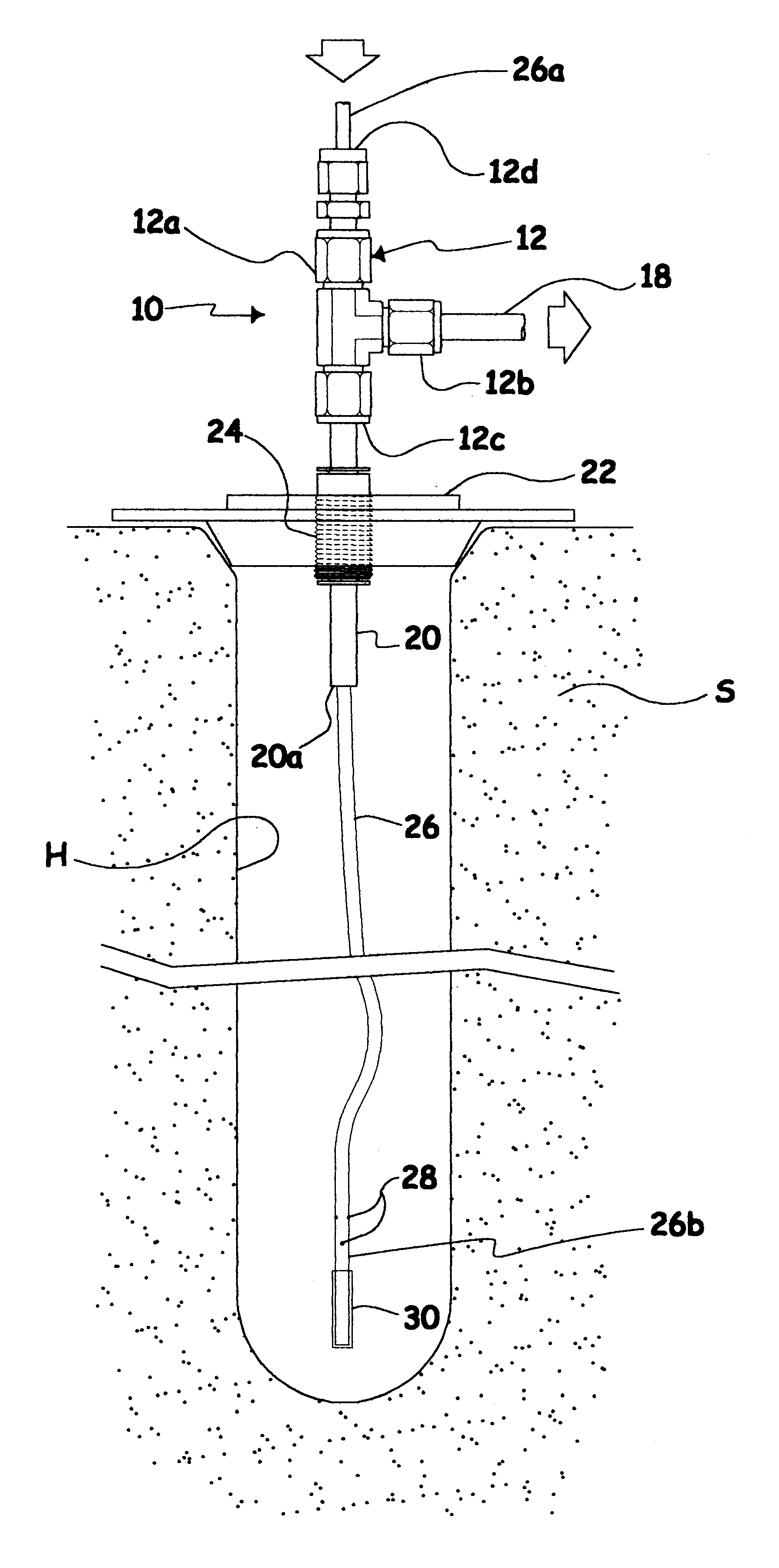
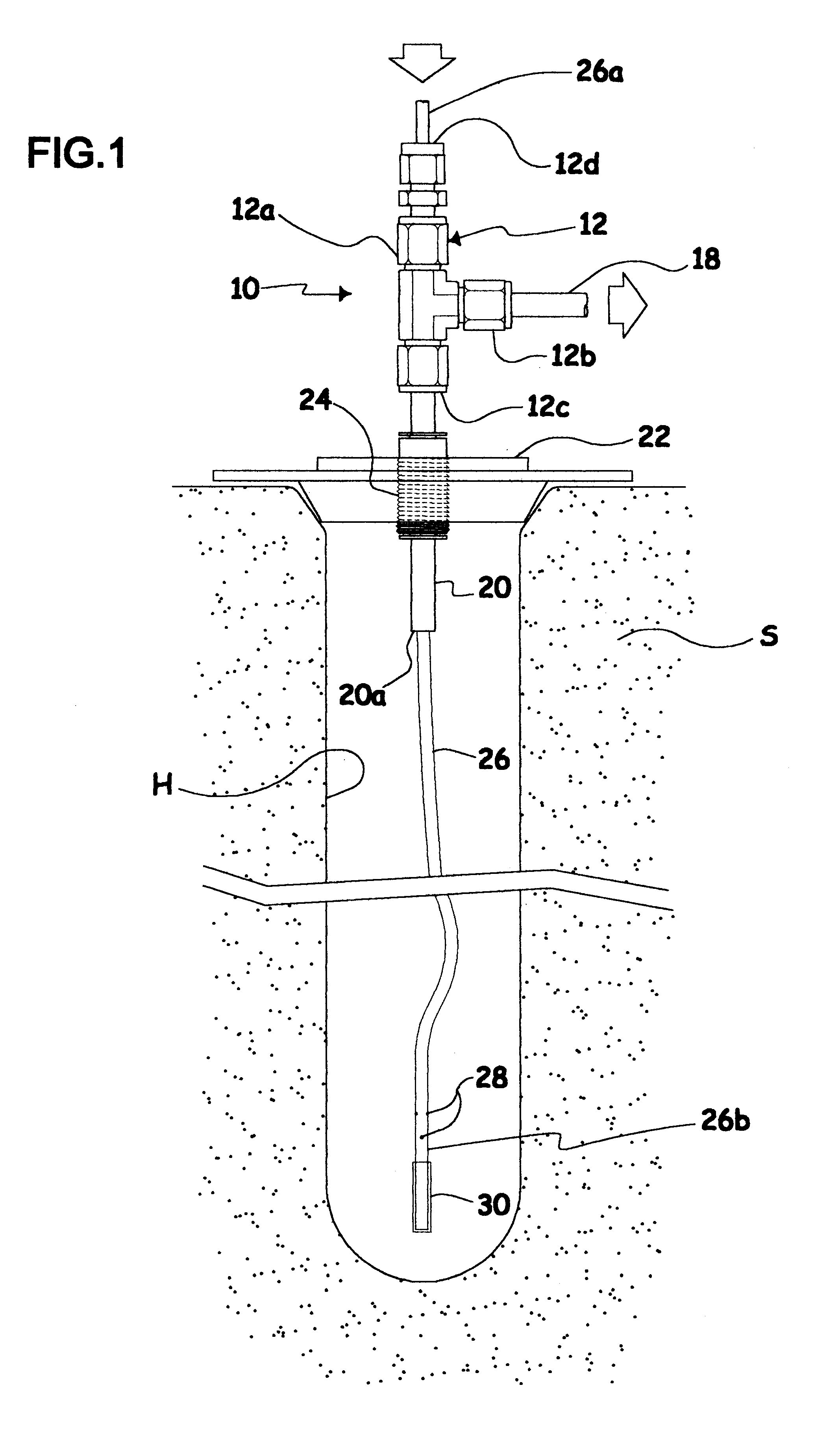
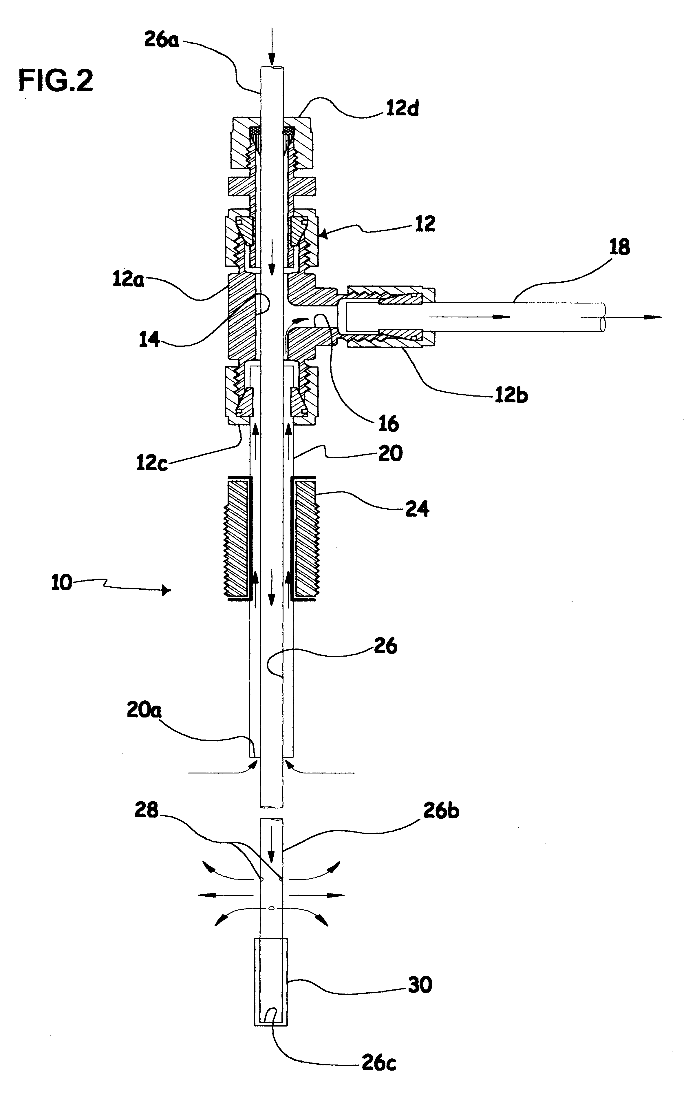
FIG. 1 shows an upwardly open ground cavity or hole H made in porous soil S in which a probe 10 used to carry out the method according to the present invention has been partly inserted. The hole H may have been made in any appropriate manner, e.g. with an auger. FIGS. 1 and 2 show that probe 10 comprises a rigid hollow T-adaptor 12 similar to the one described in the parent '888 application and which includes a vertical main body 12a and a transversely projecting side arm 12b. A first inner conduit 14 vertically extends in the T-adaptor main body 12a, and a second transverse conduit 16 located in side arm 12b is in fluid connection with first conduit 14 so as to form a T-shaped inner conduit 14, 16. A pipe 18 connected to the T-adaptor transverse arm 12b allows fluid connection between side conduit 16 and a remote fluid sample collecting device (not shown) of known construction, e.g. a commercially available testing device which simultaneously collects the fluid samples and measures...

second embodiment

In use, the probe 50 of the second embodiment is to be forcibly driven through the ground to a desired depth as shown in FIG. 3, with the encasing probe rod 54 preventing undesirable clogging of the small holes 28 of tube 26 with earth. Then, the probe rod 54 is to be upwardly partly retracted from the ground, thus creating a hole H' as shown in FIG. 4, with the sacrificial tip 58 remaining stuck into the soil at the bottom of the hole H, while tube 26 is forcibly axially slidingly displaced inside conduit 14 so that the tube lower end portion 26b remain at or near the bottom of hole H'. The circulation fluid is then ejected through holes 28, while fluid samples are continuously collected through the sleeve annular lower mouth 20a at the upper end of hole H'.

The method for testing the soil contamination according to the invention is the same with both of the above-mentioned probes 10 and 50. Indeed, it can be seen that in both cases, a hole H or H' is created about the portion of pr...


PUM


Abstract

The method is used for locally testing underground soil contamination by determining the generation rate of a first contaminant fluid in porous soil. The method includes the steps of making a hole of known dimensions in the soil, with the hole defining a first and a second spaced-apart portions; covering the hole, so as to define a closed volume in the hole; constantly injecting a second fluid in the hole at a constant given flow rate at said first portion of the hole, while simultaneously collecting fluid samples at the above-mentioned constant given flow rate at the second portion of the hole; measuring the concentrations of the first contaminant fluid from the fluid samples collected at known time intervals; and computing the generation rate of the first contaminant fluid, from the known volume of the hole and from the concentrations previously measured and originating from samples collected at the known time intervals. The probe used to carry out the above-described method has a rigid hollow body in which a semi-rigid tube is axially slidable. The probe can be driven through the ground and then partially retracted, to form a hole of known dimensions. The flexible tube is axially displaced so that its lower bored extremity is positioned near the bottom end of the hole, while the hollow rigid body of the probe has an annular opening about the tube at the upper end of the hole. The second fluid can then be circulated in the hole between the lower end of the tube and the annular opening of the probe rigid main body.

Description

The present invention relates to a method for testing soil contamination in situ.The parent U.S. application Ser. No. 09 / 11 8,888 (hereafter the '888 application) filed by the present applicant discloses a method for testing the soil contamination by ejecting a circulation fluid in the soil, with a very small proportion of a tracer fluid. Fluid samples are simultaneously collected wherein contaminant fluid concentrations and tracer fluid concentrations are measured and used for computing the effective flow rate Q', in the affected soil volume. The tracer gas is used to circumvent the fact that the value of the affected soil volume is not known. With the effective flow rate Q', the generation rate G of the contaminants in the soil can be computed. With this method according to the '888 application, the use of a tracer gas is compulsory.Also, according to the method described in the '888 application, the circulation fluid is ejected into the soil by the probe at a greater flow rate th...

Claims


Application Information

Patent Timeline
IPC IPC(8): E21B49/00E21B49/08G01N1/22G01V9/00G01N33/24G01N1/24
CPCE21B49/08G01N1/2294G01V9/007G01N33/24G01N1/24
Inventor TARTRE, ANDRE
Owner TARTRE ANDRE
Why Eureka
Try Eureka