Suction elbow provided with built-in guide blades
- Summary
- Abstract
- Description
- Claims
- Application Information
AI Technical Summary
Benefits of technology
Problems solved by technology
Method used
Image
Examples
first embodiment
(1) First Embodiment
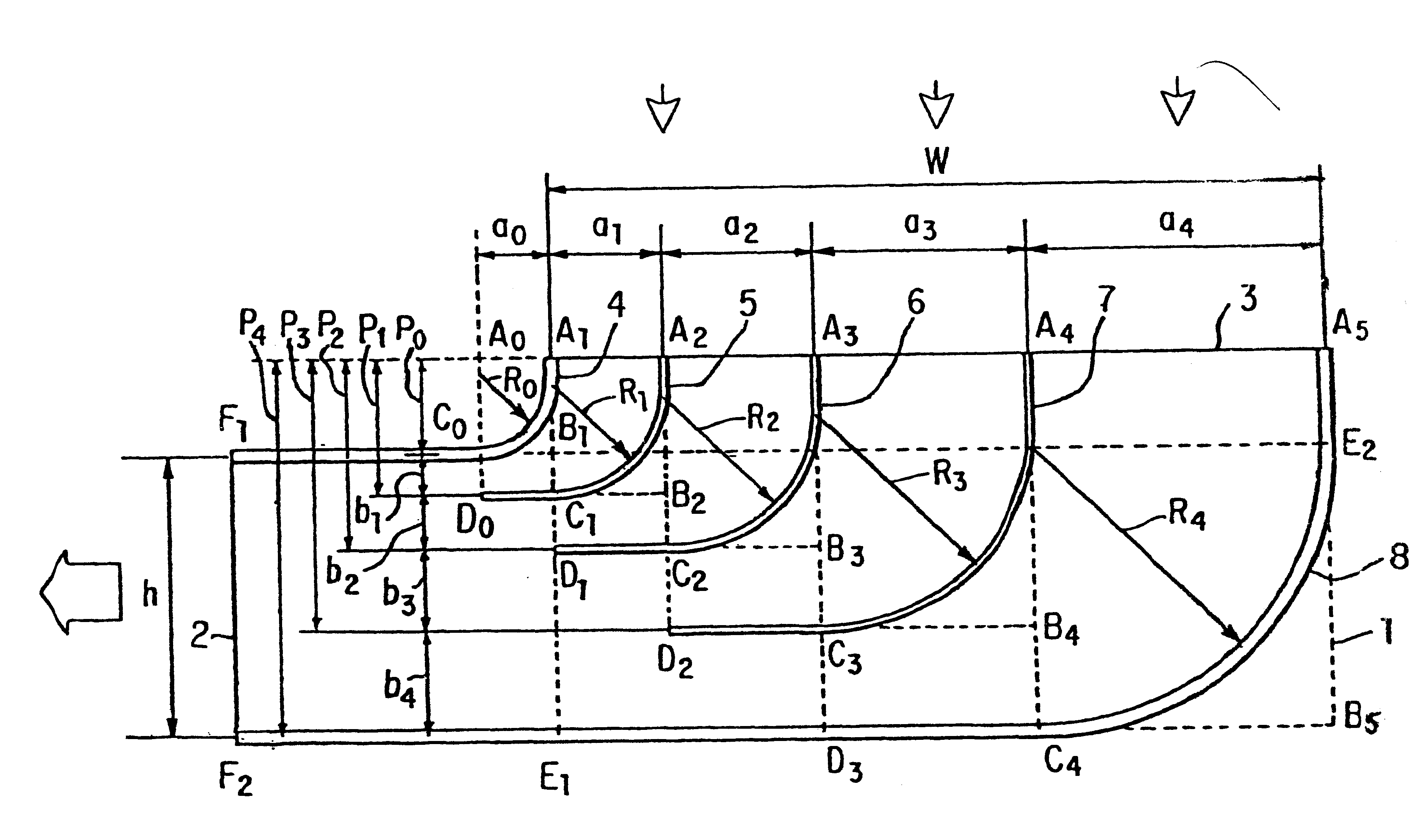
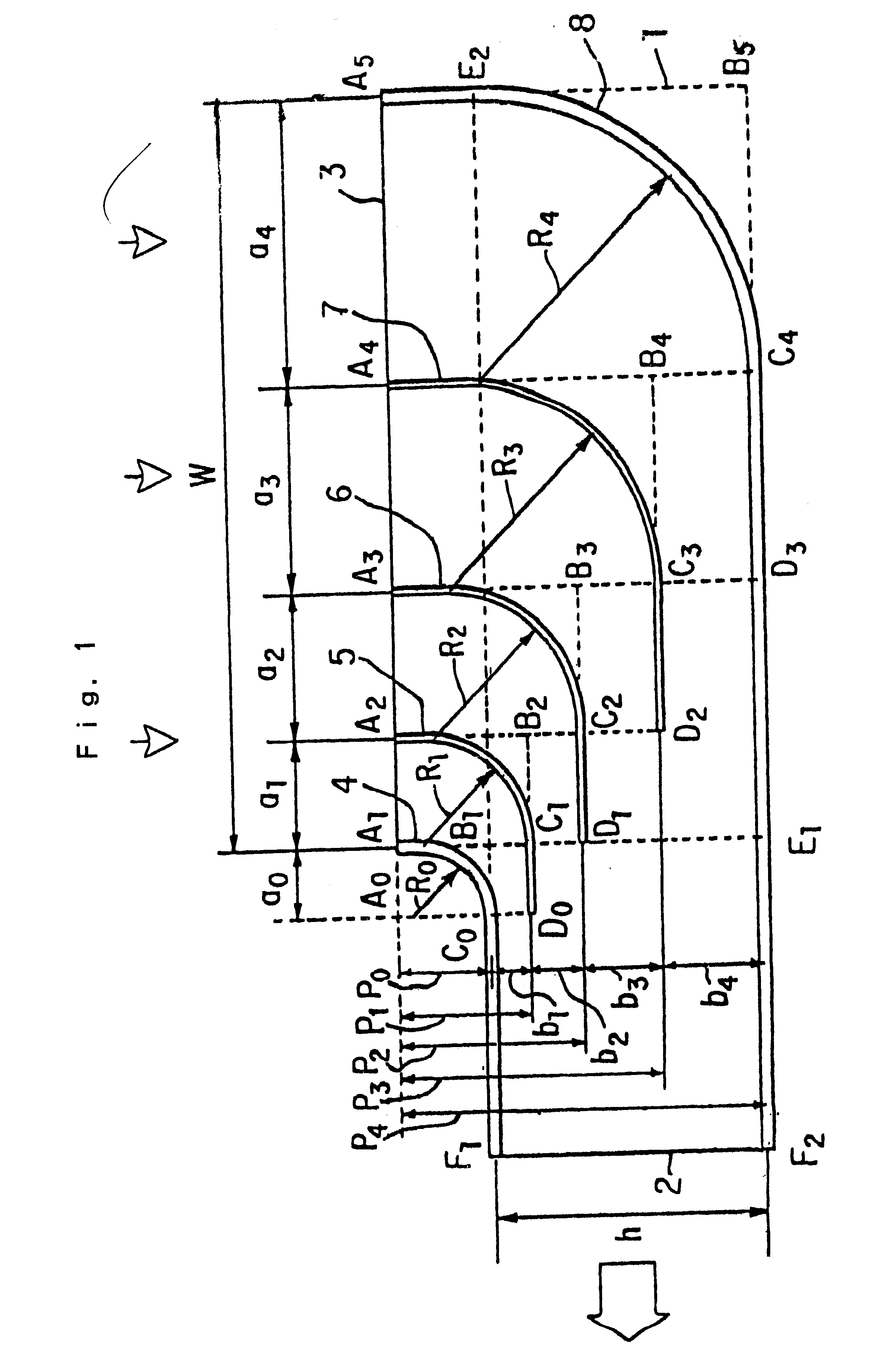
FIG. 4(a) shows a side sectional view of a suction elbow in accordance with an embodiment of the present invention, wherein the reduction ratio f is f=1 and the number m of the sub-channels is m=3. FIG. 4(b) shows a side sectional view of a suction elbow in accordance with an embodiment of the present invention, wherein the reduction ratio f is f=3 and the number m of the sub-channels is m=3. FIG. 4(c) shows a side sectional view of a suction elbow in accordance with an embodiment of the present invention, wherein the reduction ratio f is f=5 and the number m of the sub-channels is m=4. In the Figures, reference numeral 1 indicates the body of the elbow, reference numeral 2 indicates the outlet of the elbow, reference numeral 3 indicates the inlet of the elbow, reference numeral 4 indicates the inner side wall of the elbow, reference numerals 5, 6 and 7 indicate the guide vanes, and reference numeral 8 indicates the outer side wall. The outlet 2 and the inlet 3 h...
second embodiment
(2) Second Embodiment
FIG. 5(a) shows a side sectional view of a noise absorbing normal suction elbow 9 in accordance with an embodiment of the present invention, wherein the reduction ratio f is f=1 and the number m of the sub-channels is m=3. FIG. 5(b) shows a side sectional view of a noise absorbing reduction suction elbow 15 in accordance with an embodiment of the present invention, wherein the reduction ratio f is f=5 and the number m of the sub-channels is m=4. Noise absorbing members are adhered to the inner surface of outer side walls 14 and 20, the inner surface of the inner side walls 12 and 18, and the both surfaces of guide vanes 13 and 19. In the Figures, reference numerals 10 and 16 indicate elbow inlets and reference numerals 11 and 17 indicate elbow outlets.
An elbow has essentially noise absorbing effect because acoustic wave cannot pass straight through a channel in the elbow bent at right angles. In the noise absorbing suction elbows 9 and 15, a large noise absorbin...
third embodiment
(3) Third Embodiment
FIGS. 6(a) and 6(b) show an L-shaped suction elbow provided with guide vanes 21 in accordance with an embodiment of the present invention. The elbow 21 has a first suction elbow provided with guide vanes 22. The first suction elbow 22 has an inlet 23 and an outlet 24. The elbow 21 has a second suction elbow provided with guide vanes 25. The second suction elbow 25 has an inlet 26 and an outlet 27. The first suction elbow 22 and the second suction elbow 25 are connected together in tandem. The inlet 26 of the second suction elbow 25 abuts the outlet 24 of the first suction elbow 22. The outlet 27 of the second suction elbow 25 is directed at right angles to the inlet 23 of the first suction elbow 22. Reduction ratio f of the first suction elbow 22 and the second suction elbow 25 is f=5. Thus, the area ratio of the inlet 23 to the outlet 27 of the L-shaped suction elbow 21 provided with guide vanes is 25.
As shown in FIG. 3, pressure loss coefficient of the suction ...
PUM
 Abstract
Description
Claims
Application Information
 - R&D
- Intellectual Property
- Life Sciences
- Materials
- Tech Scout
- Unparalleled Data Quality
- Higher Quality Content
- 60% Fewer Hallucinations
Browse by: Latest US Patents, China's latest patents, Technical Efficacy Thesaurus, Application Domain, Technology Topic, Popular Technical Reports.
© 2025 PatSnap. All rights reserved.Legal|Privacy policy|Modern Slavery Act Transparency Statement|Sitemap|About US| Contact US: help@patsnap.com


