Disposable, multi-conduit particulate matter propelling apparatus

a propelling apparatus and multi-conduit technology, applied in dental surgery, manufacturing tools, dental tools, etc., can solve the problems of contamination of material and apparatus, increased overall size of existing devices, and bulky nozzles made of expensive carbide alloys,

Inactive Publication Date: 2001-09-25
HERTZ REUBEN +1
View PDF16 Cites 31 Cited by
  • Summary
  • Abstract
  • Description
  • Claims
  • Application Information

AI Technical Summary

Problems solved by technology

These functional characteristics require that existing devices have larger overall sizes and bulky nozzles made of expensive carbide alloys.
This presents an opportunity for unit malfunction, for contamination of the material and apparatus, and for loading with inappropriate and even dangerous particulate material by mistake.
Problems with Fernwood are that it is too costly to be disposable; it draws particulate matter from a container using a vacuum rather than by more efficient blow through mixing of as per our invention, and is thus sensitive to variations in material and gas moisture levels, and requires an unclogging mechanism.
Fernwood operates at relatively high pressures, 80-100 psi, requiring a special tap into the air-lines and limiting the range of operational pressures.
In addition, Fernwood requires special training to set up and use, cannot be cost effectively and completely sterilized between uses, cannot deliver varying sizes of particles, and is contaminated after every use.
Each of the prior art is limited wherein the application is specific to propelling dry particulate matter.

Method used


Image

  • Disposable, multi-conduit particulate matter propelling apparatus
  • Disposable, multi-conduit particulate matter propelling apparatus
  • Disposable, multi-conduit particulate matter propelling apparatus

Examples


Embodiment Construction

As required, detailed embodiments of the present invention are disclosed herein; however, it is to be understood that the disclosed embodiments are merely exemplary of the invention that may be embodied in various forms. Therefore, specific structural and functional details disclosed herein are not to be interpreted as limiting, but merely as a basis for the claims and as a representative basis for teaching one skilled in the art to variously employ the present invention in virtually any appropriately detailed structure.

Reference is now made to the drawings, wherein like characteristics and features of the present invention shown in the various figures are designated by the same reference numerals.

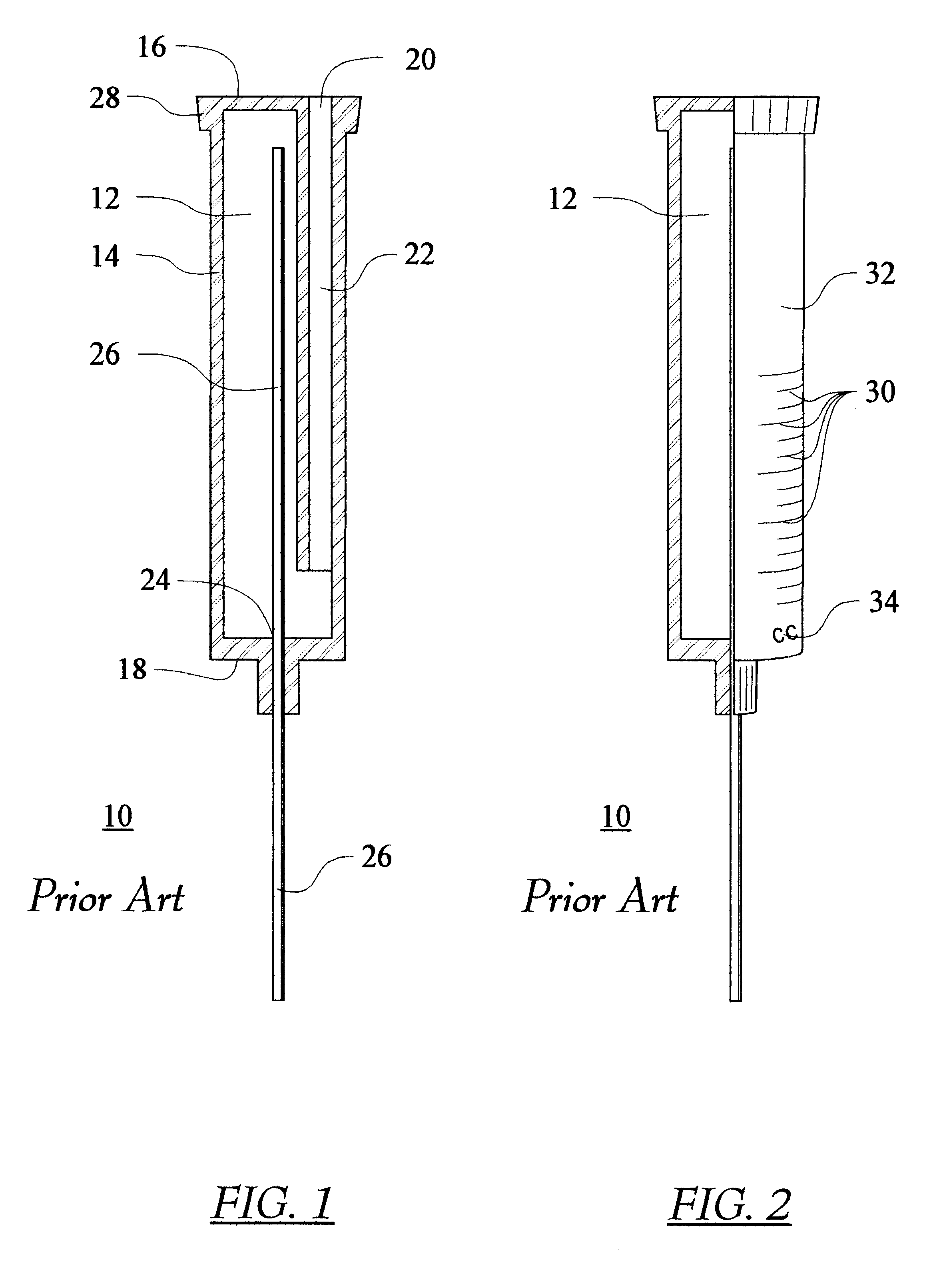
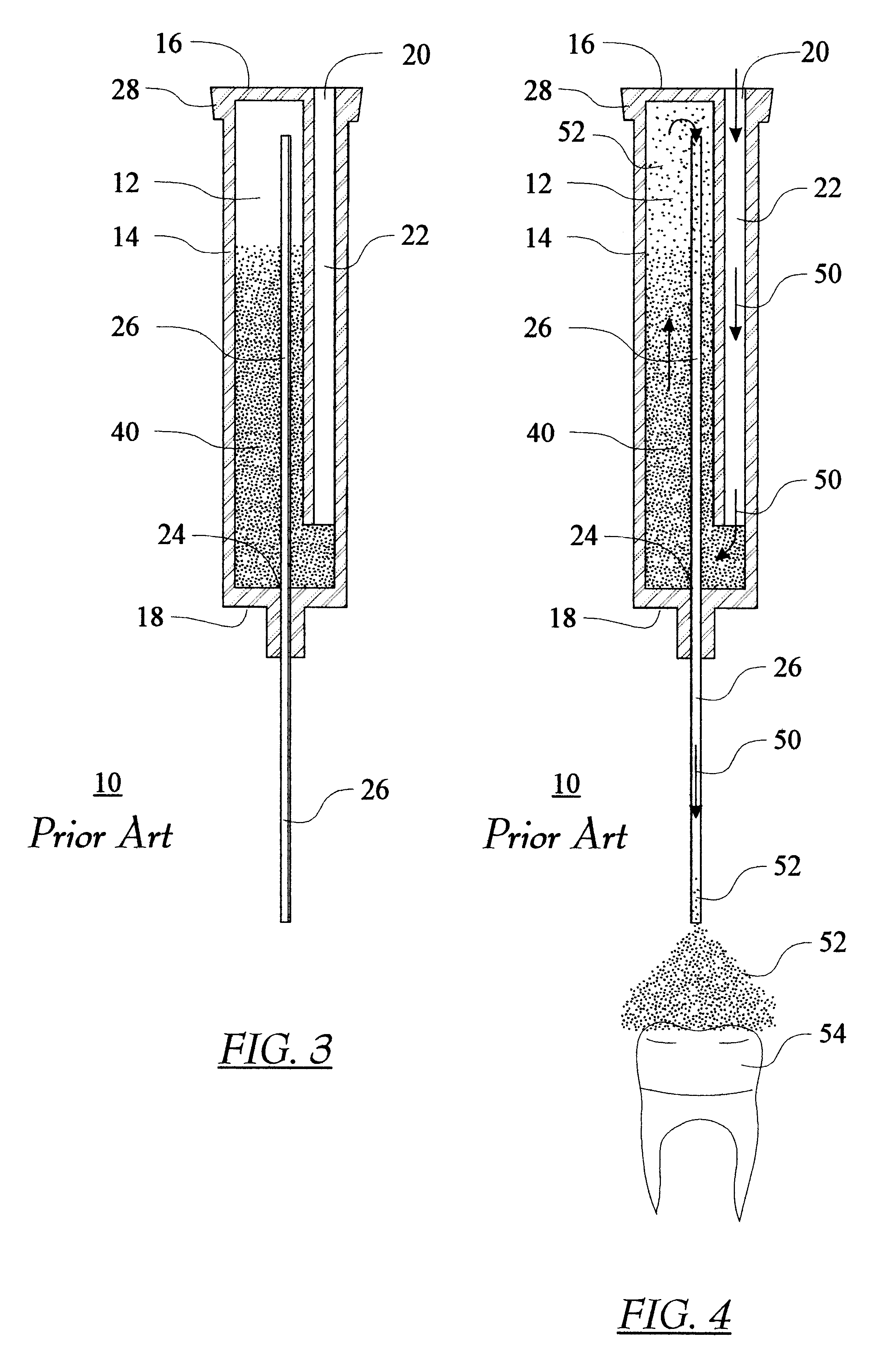
FIGS. 1-4 illustrate the apparatus and operation of the Applicant's prior art, U.S. Pat. No. 5,839,946, issued Nov. 24, 1998.

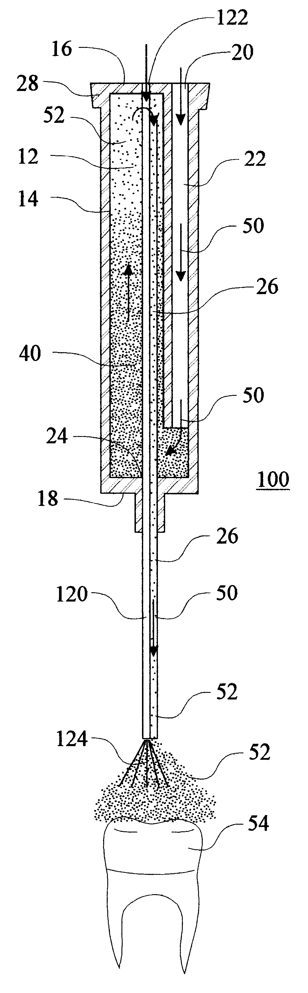
FIG. 1 illustrates a cross sectional view of a single-conduit, disposable particle propelling apparatus 10 for propelling particulate matter (not shown) against targ...


PUM


Abstract

A disposable apparatus for propelling particulate matter against a surface of a target material includes, a mixing chamber having a chamber wall, a multi-conduit receiving port, a propellant-gas receiving conduit, a discharge conduit, and a flow through conduit. The gas delivery conduit extends from the propellant-gas receiving port into the chamber, a mixture discharge conduit extending from the mixture discharge port into the chamber, and a quantity of particulate matter inside the chamber. The flow through conduit(s) provide a means for transferring flow from the multi-conduit receiving port through the discharge wall to exit proximate the exit of the discharge port. A method is provided for propelling particulate matter against a surface of a target material using the above-described apparatus, including the steps of delivering a stream of gas into the air delivery conduit and into the mixing chamber from the gas source, so that the gas stream blows through the quantity of particulate matter, causing the particulate matter to mix with the gas stream, forming a gas and particle mixture, and discharging the mixture through the discharge conduit and the discharge port to strike the surface of the target material. The method further provides a means for transferring a second (or more) flow through the apparatus. The multiple flows can be externally mixed to increase the versatility of the apparatus. The end of the discharge conduit(s) can be designed to modify the discharge flow of the medium.

Description

The present invention relates generally to the field of devices for propelling particulate matter, air, and fluid against a surface of target material to rinse, wash, sand-blast, abrade, etch, erase, cut, smooth, clean, polish and harden the surface. More specifically, the present invention relates to a totally disposable, inexpensive particle propelling apparatus serviced by a multi-conduit fluid supply system. The multi-conduit fluid supply system is known and commonly available in dental offices and laboratories. One such multi-flow system provides high-pressure water flow, high-pressure air, low-pressure air, and exhaust. The apparatus provides a means for mixing particulate matter with compressed air; the compressed air enters through a gas delivery port, mixes within the primary chamber, and discharges through a mixture discharge port and directed at the desired object via a particle directing hollow tube. The apparatus further provides a means for incorporating at least one o...

Claims


Application Information

Patent Timeline
Patent Type & Authority Patents(United States)
IPC IPC(8): A61C3/02A61C3/025B24C5/02B24C5/00B24C7/00
CPCA61C3/025B24C7/0046B24C5/02
Inventor HERTZ, REUBENHERTZ, ALLEN D.
Owner HERTZ REUBEN
Why Eureka
Try Eureka