Heat sealer for synthetic resin bag

Inactive Publication Date: 2001-10-16
ISHIDA CO LTD
View PDF10 Cites 33 Cited by
  • Summary
  • Abstract
  • Description
  • Claims
  • Application Information

AI Technical Summary

Problems solved by technology

This lack of the capability of quickly compensating for reduction in temperature has long led to reduction in sealing strength in that portion of the transverse seal which is aligned with the longitudinal sealed portion in the tubular sheet S.
Also, since the temperature sensor 28 is positioned offset from the path of direct transmission of heat from the heaters to the adjacent sheet contact faces in the respective presser pieces, the actual temperature at the sheet contact faces considerably differs from the temperature measured by the temperature sensor, making it difficult to control the temperature of the sheet contact faces accurately and with high precision.
Furtherm

Method used


Image

  • Heat sealer for synthetic resin bag
  • Heat sealer for synthetic resin bag
  • Heat sealer for synthetic resin bag

Examples


first preferred embodiment-- figs

First Preferred Embodiment--FIGS. 1A to 5

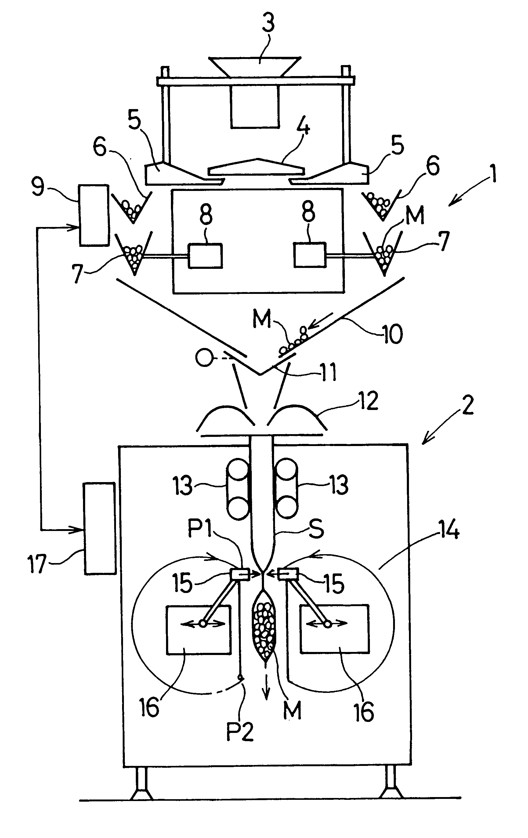
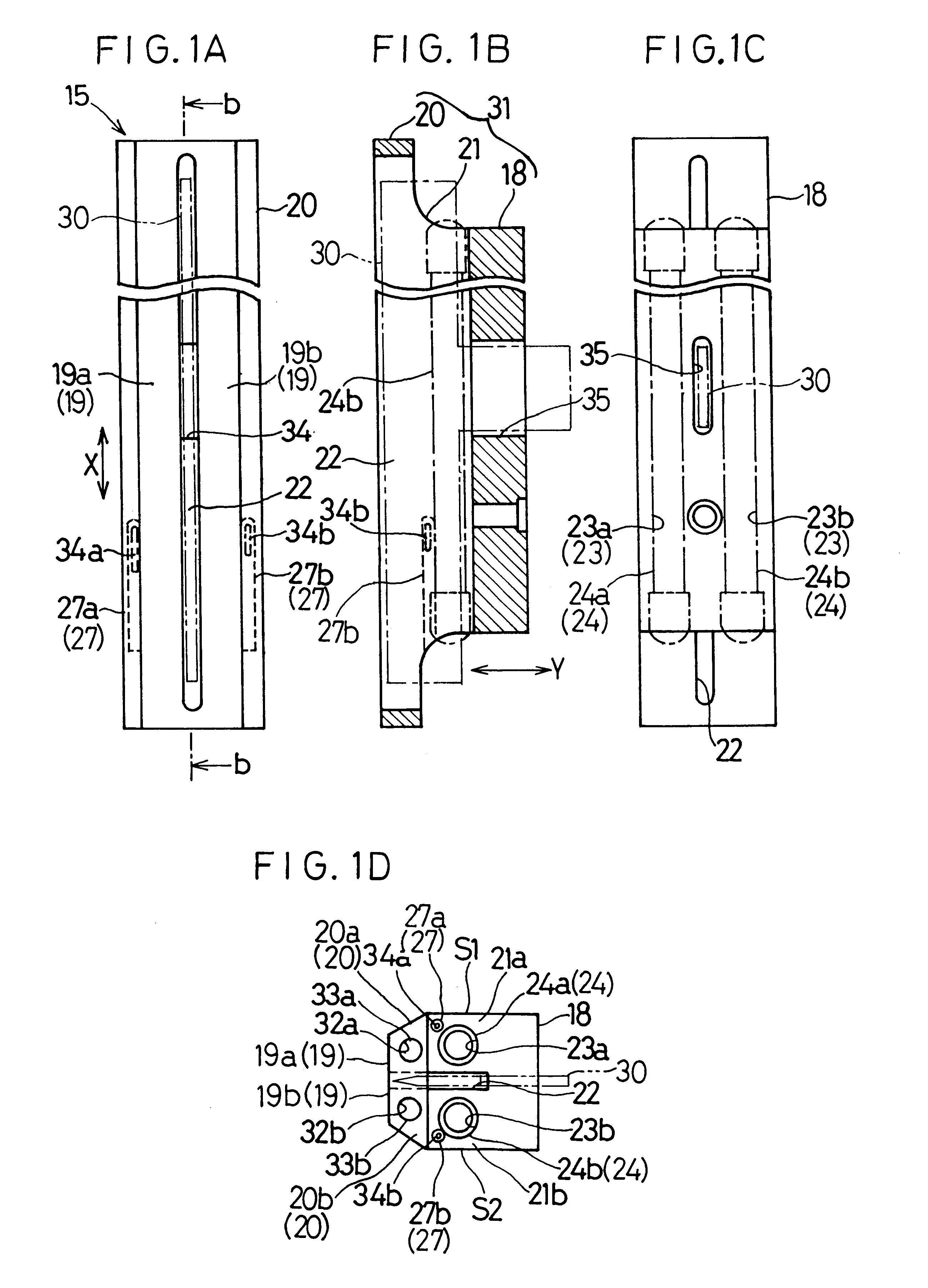
Referring first to FIGS. 1A to 1D, the transverse heat-sealing jaw 15 shown therein comprises a one-piece block 31 made of a metallic material having a high rigidity such as a ferrous material, for example, stainless steel and including a support section 18 adapted to be supported by the drive means 16 (FIG. 10) which forms a part of the pressing mechanism, a press section 20 having upper and lower sheet contact faces 19a and 19b defined therein, and a connecting section 21 connecting the press section 20 to the support section 18 with the upper and lower sheet contact faces 19a and 19b oriented in a direction away from the support section 18.

In this one-piece block 31, the press section 20 is formed with a cutter groove 22 traversing a fill width of the one-piece block 31 in a direction shown by the arrow while extending inwardly of the one-piece block 31 from a point substantially intermediate between the upper and lower sheet contact faces...

second preferred embodiment-- figs.6a and 6b

Second Preferred Embodiment--FIGS. 6A and 6B

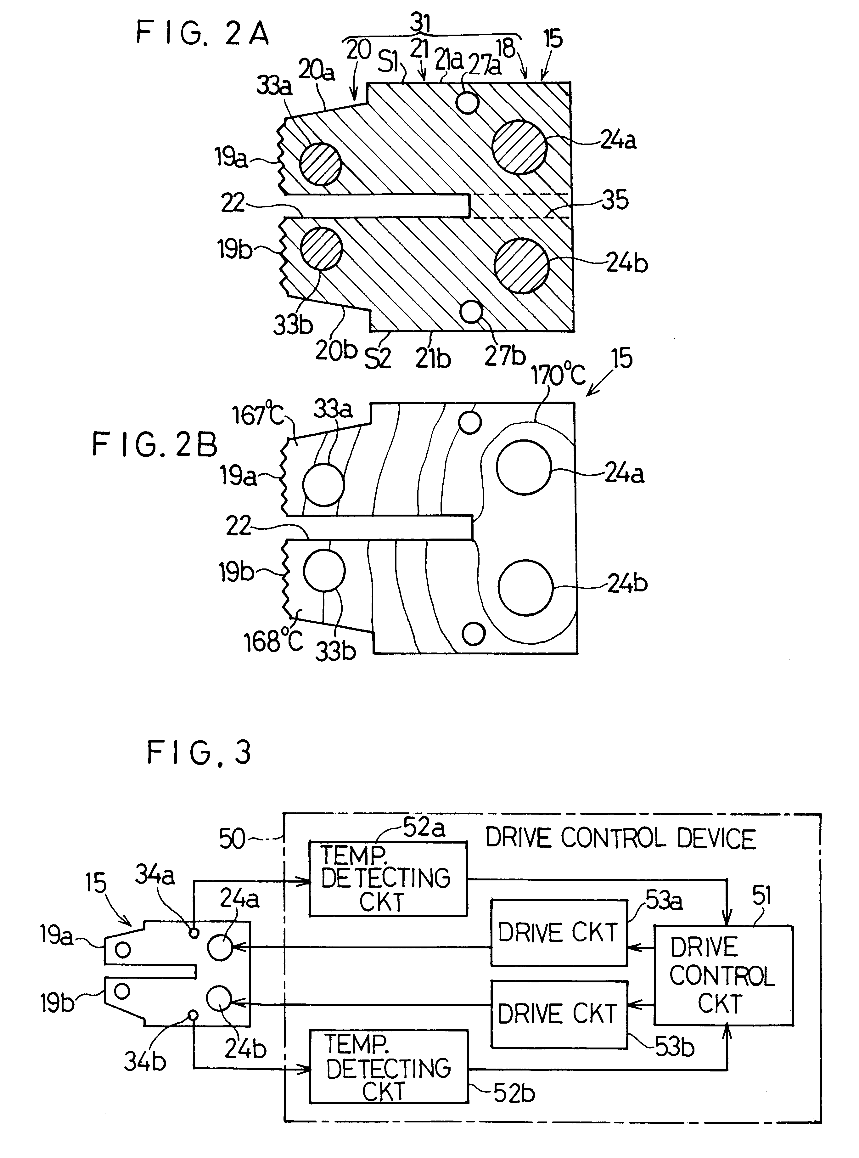
The transverse heat-sealing jaw 15 according to the second preferred embodiment of the present invention differs from that according to the first preferred embodiment in that each of the upper and lower heat conducting members 33a and 33b is employed in the form of a metallic pipe of a high heat conducting property made of, for example, copper and having a relatively large wall thickness and that the corresponding temperature sensors 34a and 34b are inserted into the heat conducting members 33a and 33b to occupy a position aligned with the intermediate portion of the associated sheet contact faces 19a and 10b.

According to the second preferred embodiment, since the temperature sensors 34a and 34b can directly measure the respective temperatures at the intermediate portions of the upper and lower sheet contact faces 19a and 19b, the accuracy of measurements at the intermediate portions can be increased considerably and, therefore, the contro...

third preferred embodiment-- figs.7a and 7b

Third Preferred Embodiment--FIGS. 7A and 7B

In this third preferred embodiment shown specifically in FIG. 7A, the upper and lower rod heaters 24a and 24b are arranged in the upper and lower connecting arms 21a and 21b, respectively, and, at the same time, the upper and lower sensor holes 27a and 27b are defined in the upper and lower connecting arms 21a and 21b at respective locations between the upper and lower rod heaters 24a and 24b and the upper and lower sheet contact faces 19a and 19b with most of each of the upper and lower sensor holes 27a and 27b positioned outside a generally triangular heat conductive region A1 and A2. The triangular heat conductive region A1 in the upper connecting arm 21a is defined as bound between two imaginary lines passing in touch with upper and lower edges 41 and 42 (extending in the direction X) of the upper contact face 19a, respectively, and converging at an angle .theta.a at the longitudinal center Oa of the upper rod heater 24a, whereas the tr...


PUM

PropertyMeasurementUnit
Poweraaaaaaaaaa
Temperatureaaaaaaaaaa
Lengthaaaaaaaaaa

Abstract

A heat sealer capable of providing a high sealing strength by appropriating a distribution of temperature at two sheet contact faces (19a, 19b) includes a block (31) made of a metallic material having a high rigidity and operable to heat the resinous sheet (S) while pressing the latter. The block (31) is provided with heaters (24a, 24b) therein and also with heat conducting members (33a, 33b) each having an excellent heat conductive characteristic higher than that of the metallic material. The heat conducting members (33a, 33b) are positioned between the heaters (24a, 24b) and the sheet contact faces (19a, 19b), respectively.

Description

1. Field of the InventionThe present invention generally relates to a heat sealer of a type capable of heat-sealing a sheet of a synthetic resin to form a bag and, more particularly, to horizontal and vertical sealing jaw assemblies for accomplishing horizontal and vertical seals, respectively.2. Description of the Prior ArtThe prior art weighing and packaging system will first be discussed with reference to FIG. 10 since the heat sealer to which the present invention pertains is generally employed in such weighing and packaging system. As shown in FIG. 10, the weighing and packaging system comprises a weighing apparatus 1 and a packaging machine 2 for successively packaging articles M, that are successively discharged from the weighing apparatus 1, with a sheet of a synthetic resin by forming such resinous sheet into bags one for each article M. Each article M may be one or a quantity of edible or non-edible items, for example, potato chips, fruits, candies, vegetables, screws, nai...

Claims


Application Information

Patent Timeline
IPC IPC(8): B29C65/74B29C65/18B65B9/20B65B51/10
CPCB29C65/18B29C66/849B29C66/80B29C66/81435B29C66/83543B29C66/91231B29C66/919B29C65/305B29C66/91421B29C66/9161B29C66/81427B29C66/1122B29C66/4312B29C66/91212B29C66/961B29C66/81431B29C65/7451B29C66/91423B29C66/8181B29C66/81419B29C66/9192
Inventor NAKAMURA, YOSHIHIROMORINAKA, HIROAKI
Owner ISHIDA CO LTD
Why Eureka
Try Eureka