Folded cavity-backed slot antenna

a slot antenna and cavity-back technology, applied in the field of slot antennas, can solve the problems of not being able to provide accurate circular polarization, not being compact enough for use in a wide-scan phased array antenna, and not being able to handle very high average power levels,

Inactive Publication Date: 2001-10-16
RAYTHEON CO
View PDF15 Cites 39 Cited by
  • Summary
  • Abstract
  • Description
  • Claims
  • Application Information

AI Technical Summary

Problems solved by technology

However, none of the presently available antennas, compact enough for use in a wide-scan phased array antenna, are capable of handling very high average power levels while simultaneously providing very accurate polarization, e.g., circular polarization, over a very large angular region (e.g., + / -50.degree. in both planes).
Circularly polarized patch antennas can be made smaller than one-half of a free-space wavelength, but only through the use of a dielectric, thereby rendering the patch antenna inadequate for high power applications.
Although such an antenna design can handle high power levels, it is not capable of providing accurate circular polarization.
The size of a conventional cavity-backed slot antenna can be reduced by filling the cavity with a dielectric material, but this introduces substantial losses and renders the antenna inadequate for high average power applications.
However, the antennas disclosed in these patents are either too Large, have poor circular polarization performance, and / or can not handle high power levels.

Method used


Image

  • Folded cavity-backed slot antenna
  • Folded cavity-backed slot antenna
  • Folded cavity-backed slot antenna

Examples


Embodiment Construction

Illustrative embodiments and exemplary applications will now be described with reference to the accompanying drawings to disclose the advantageous teachings of the present invention.

While the present invention is described herein with reference to illustrative embodiments for particular applications, it should be understood that the invention is not limited thereto. Those having ordinary skill in the art and access to the teachings provided herein will recognize additional modifications, applications, and embodiments within the scope thereof and additional fields in which the present invention would be of significant utility.

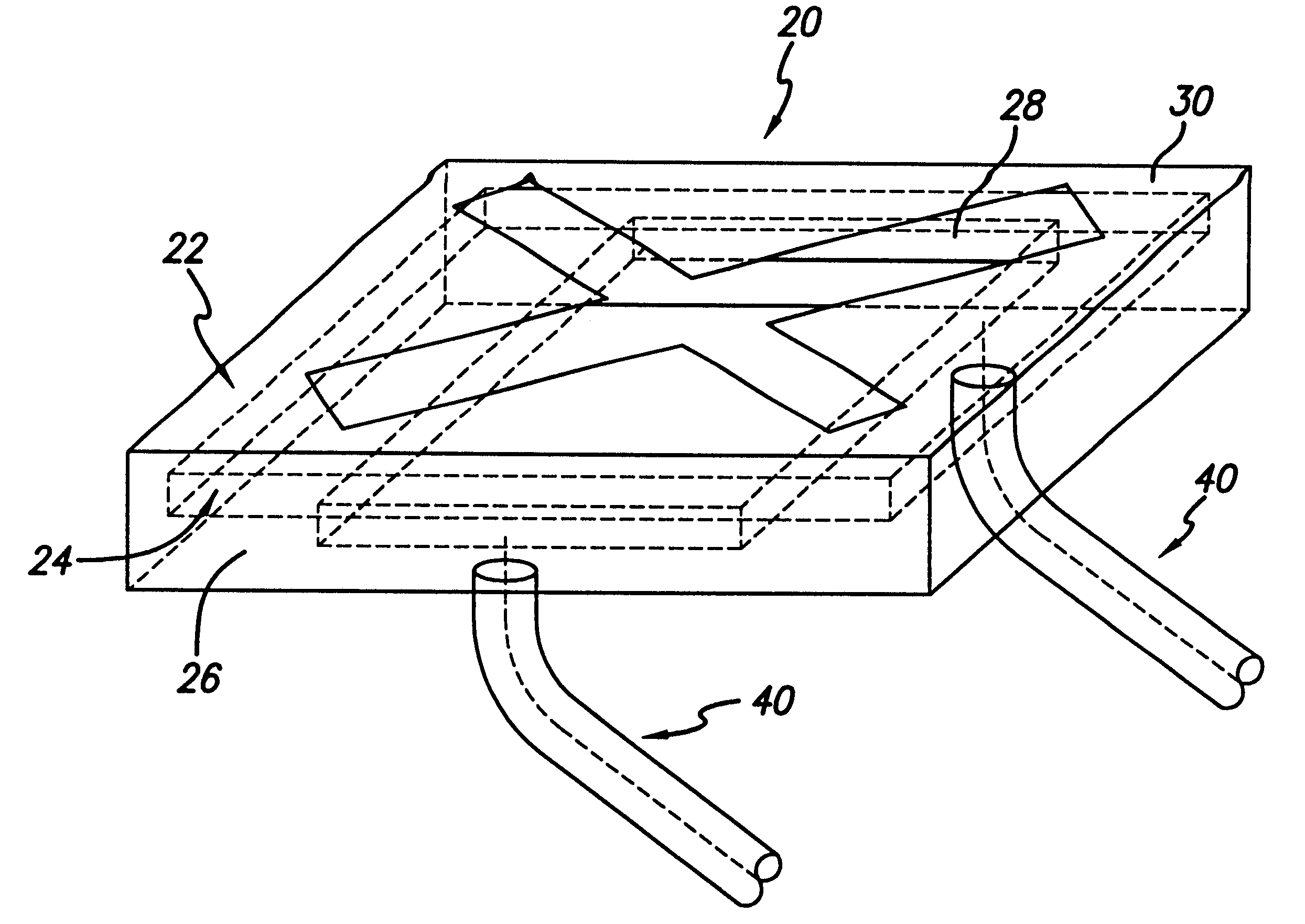
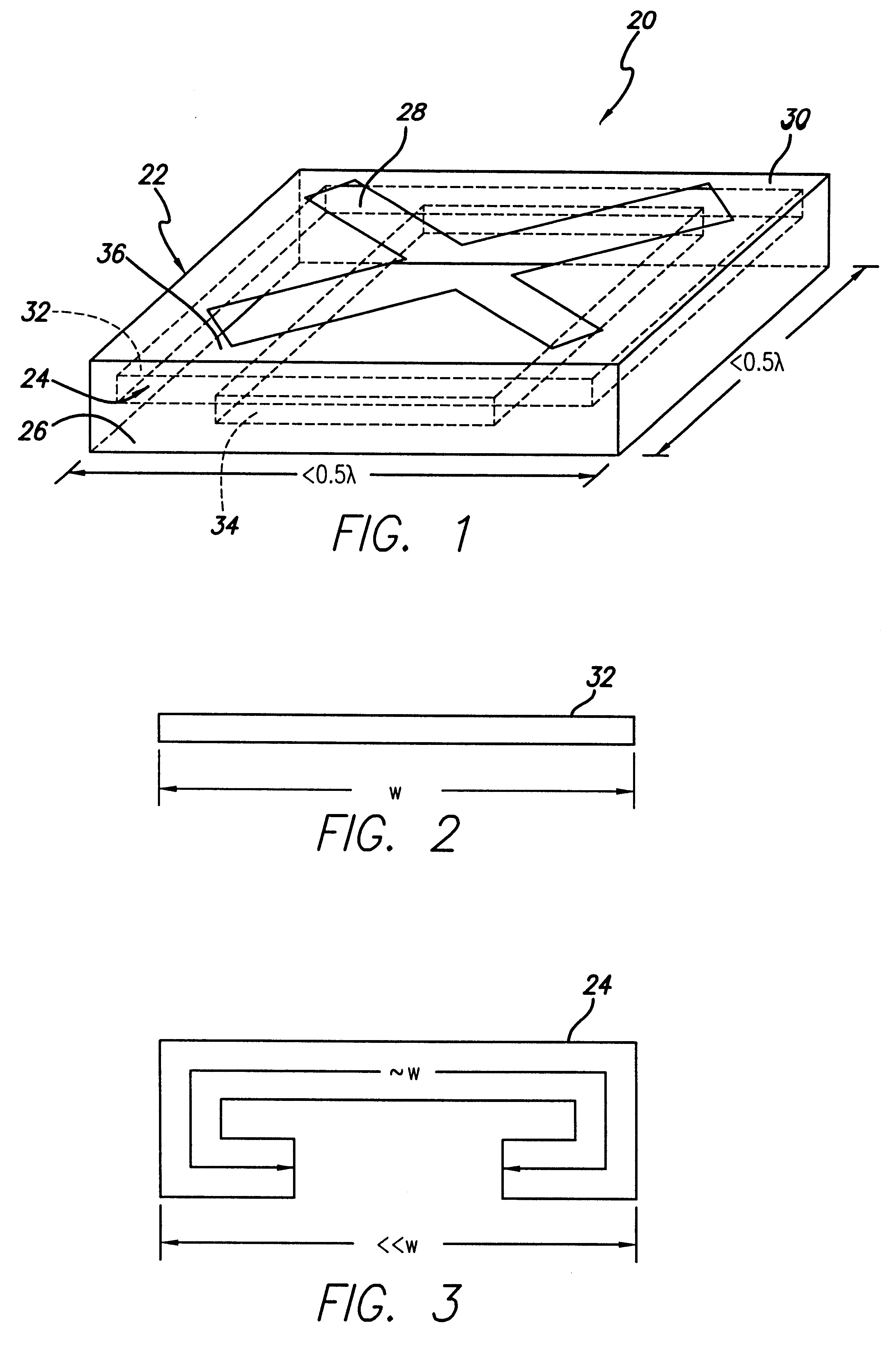
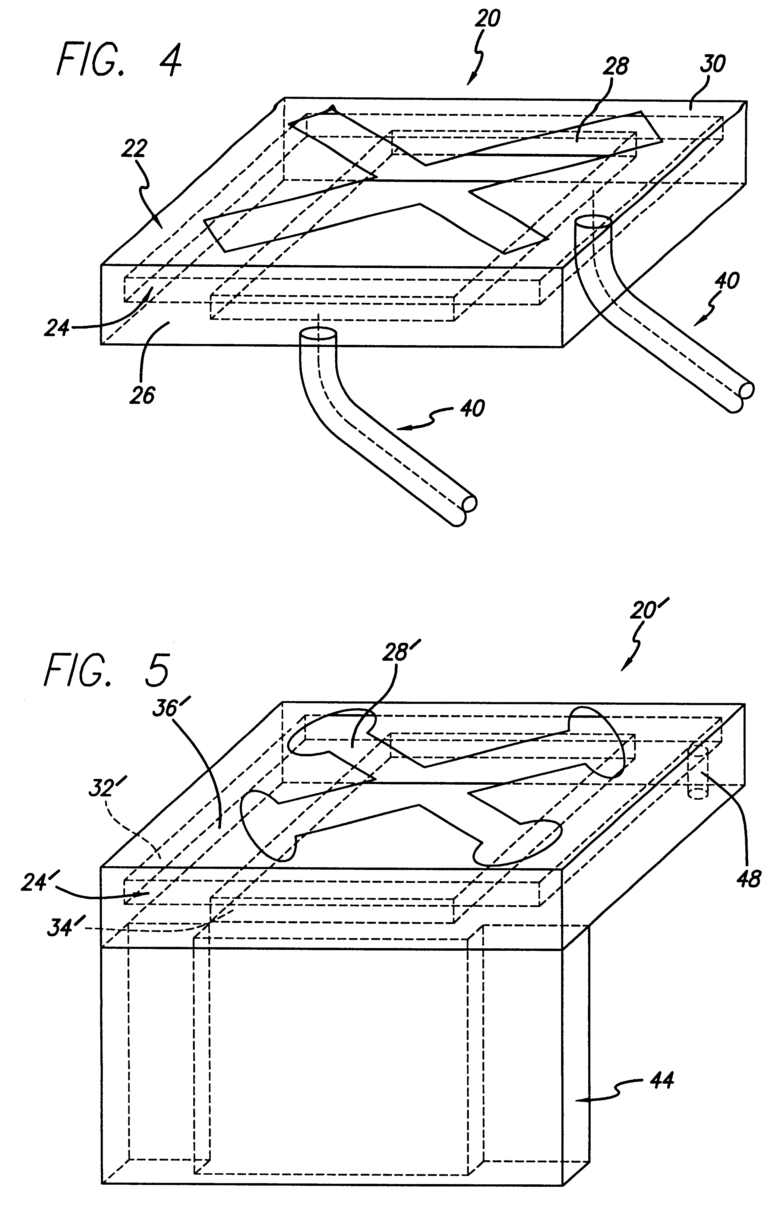
With reference now to FIG. 1, there can be seen an isometric view of a folded cavity-backed slot antenna 20 of an exemplary embodiment of the present invention. The folded cavity-backed slot antenna 20 includes a housing 22 that has a folded rectangular cavity 24 formed in a bottom cavity wall 26 in accordance with a novel aspect of the present invention, and a ...


PUM


Abstract

An antenna that includes a housing having a plurality of walls forming an enclosure, a slot formed in a first wall of the housing, and, a folded cavity formed in a second wall of the housing opposite the first wall. The folded cavity is preferably a compound cavity that includes a first cavity portion and a second cavity portion joined around their entire respective peripheries by a fold or shelf. Any convenient RF transmission line, e.g., a waveguide or coaxial cables, can be used to inject RF energy into the folded cavity. In certain embodiments, both the width and length of the housing are each less than ½ of a free-space wavelength, and the antenna is capable of producing very accurate circular polarization and is capable of handling very high power levels, e.g., 10 kW, thereby making it suitable for high power applications which require extremely compact antenna elements, e.g., wide-scan phased array antennas.

Description

1. Field of the InventionThe present invention relates to antennas. More specifically, the present invention relates to slot antennas used in high-power applications.2. Description of the Related ArtThe individual antenna elements of a wide-scan phased array antenna (e.g., one capable of scanning very wide angles such as + / -45.degree.) must typically be spaced very close together. More specifically, the individual antenna elements must generally be spaced approximately one-half of a free-space wavelength apart from one another. There are a variety of antenna elements that are of such compact design. However, none of the presently available antennas, compact enough for use in a wide-scan phased array antenna, are capable of handling very high average power levels while simultaneously providing very accurate polarization, e.g., circular polarization, over a very large angular region (e.g., + / -50.degree. in both planes). In this connection, there are a number of applications, including...

Claims


Application Information

Patent Timeline
Patent Type & Authority Patents(United States)
IPC IPC(8): H01Q13/10H01Q21/06H01Q13/18
CPCH01Q13/18H01Q21/064
Inventor BROWN, KENNETH W.DRAKE, THOMAS A.
Owner RAYTHEON CO
Why Eureka
Try Eureka