Testing telecommunications equipment

a technology for telecommunication equipment and quality assessment, applied in the direction of substation equipment, electrical equipment, surveillance/monitoring/testing arrangements, etc., can solve the problems of affecting the application of telecommunications equipment in the live telephone network, affecting the quality of communication systems, and exhibiting far more complex effects of modern networks

Inactive Publication Date: 2001-10-16
PSYTECHNICS
View PDF10 Cites 52 Cited by
  • Summary
  • Abstract
  • Description
  • Claims
  • Application Information

AI Technical Summary

Problems solved by technology

Modern networks exhibit far more complex effects and contain elements such as speech switches and compressive codecs that are highly non-linear and time varying.
The need to use a number of subjects for this kind of assessment makes the techniques expensive and hinders or prevents their application in the `live` telephone network.
However, these tests neglect the reactions of users to the system's behaviour, which in turn can influence the way the system performs.
In contrast, conventional engineering metrics such as signal-to-noise ratio do not in general correlate well with speech quality.
However, these characteristics affect the conversational pattern.
Furthermore, a fixed conversational pattern does not take into account the human response to losses in the line, such as noise, delay or freeze-out (the loss of a signal, for example due to capacity problems in the network, or delays in response to the start of a signal), which may be random in nature.
(Of course, this reply may itself be corrupted in transmission, causing the other device in turn to respond in some other way than this intenti

Method used


Image

  • Testing telecommunications equipment
  • Testing telecommunications equipment
  • Testing telecommunications equipment

Examples


Embodiment Construction

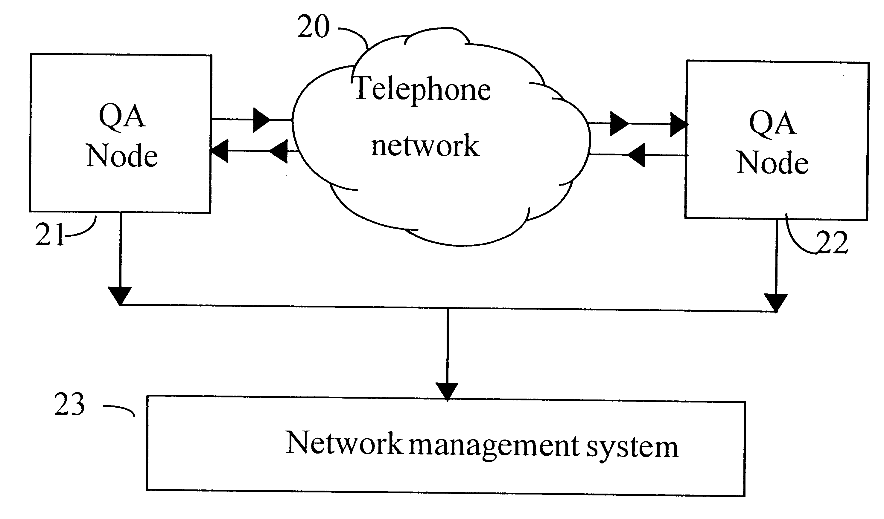
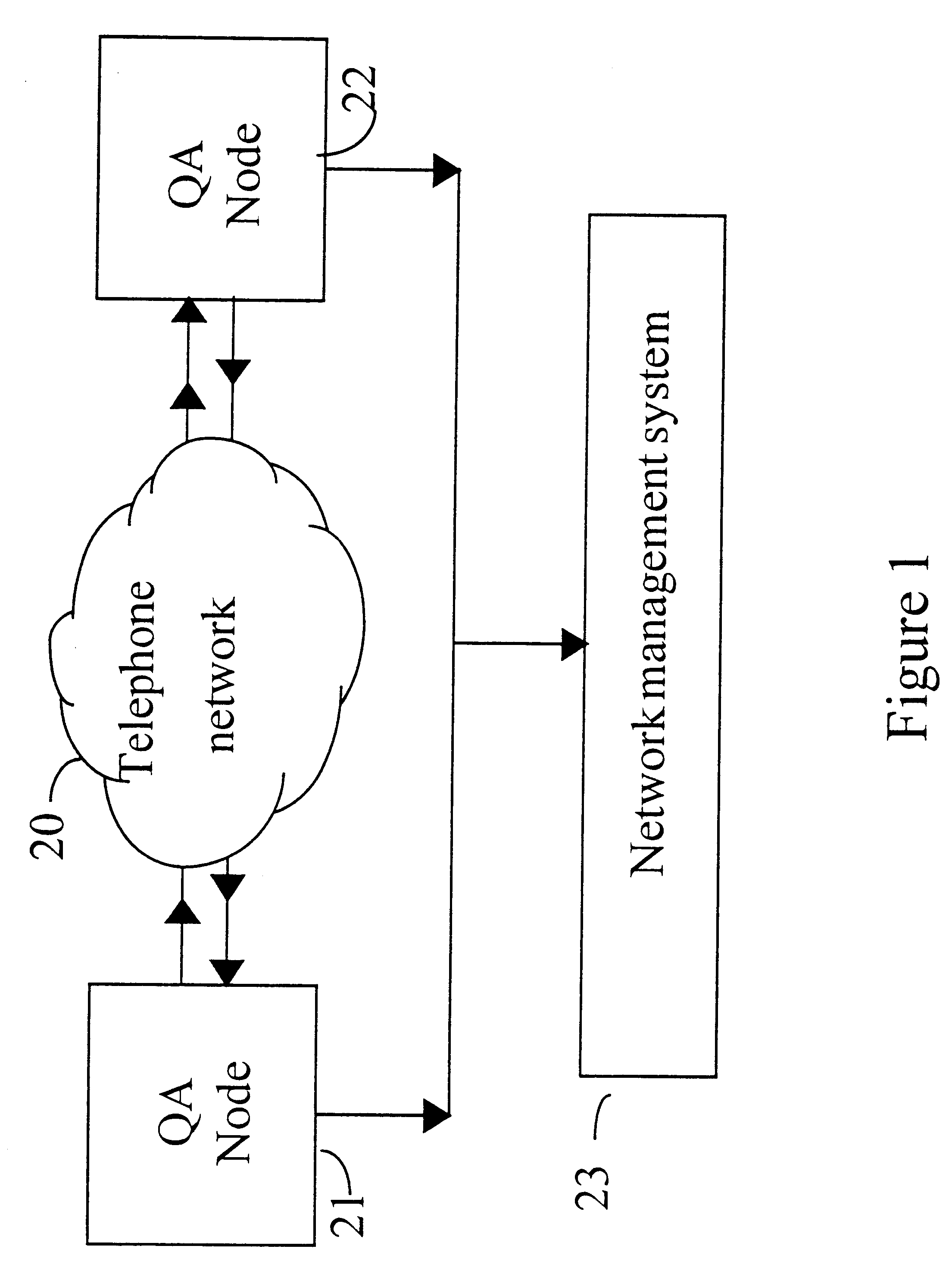
An outline structure for a quality assessment (QA) system with two devices is shown in FIG. 1. As shown in FIG. 1, at each termination 21, 22 of the network 20 under test there is located a measurement device or tester. One device (the `originator`) 21 sets up calls as appropriate and initiates a conversation with one or more receiving devices (`destinations`) 22 (only one shown); assessment of an audioconference link would require one such device for each party to the call. Once conversation is initiated all devices 21, 22 etc behave in a similar way.

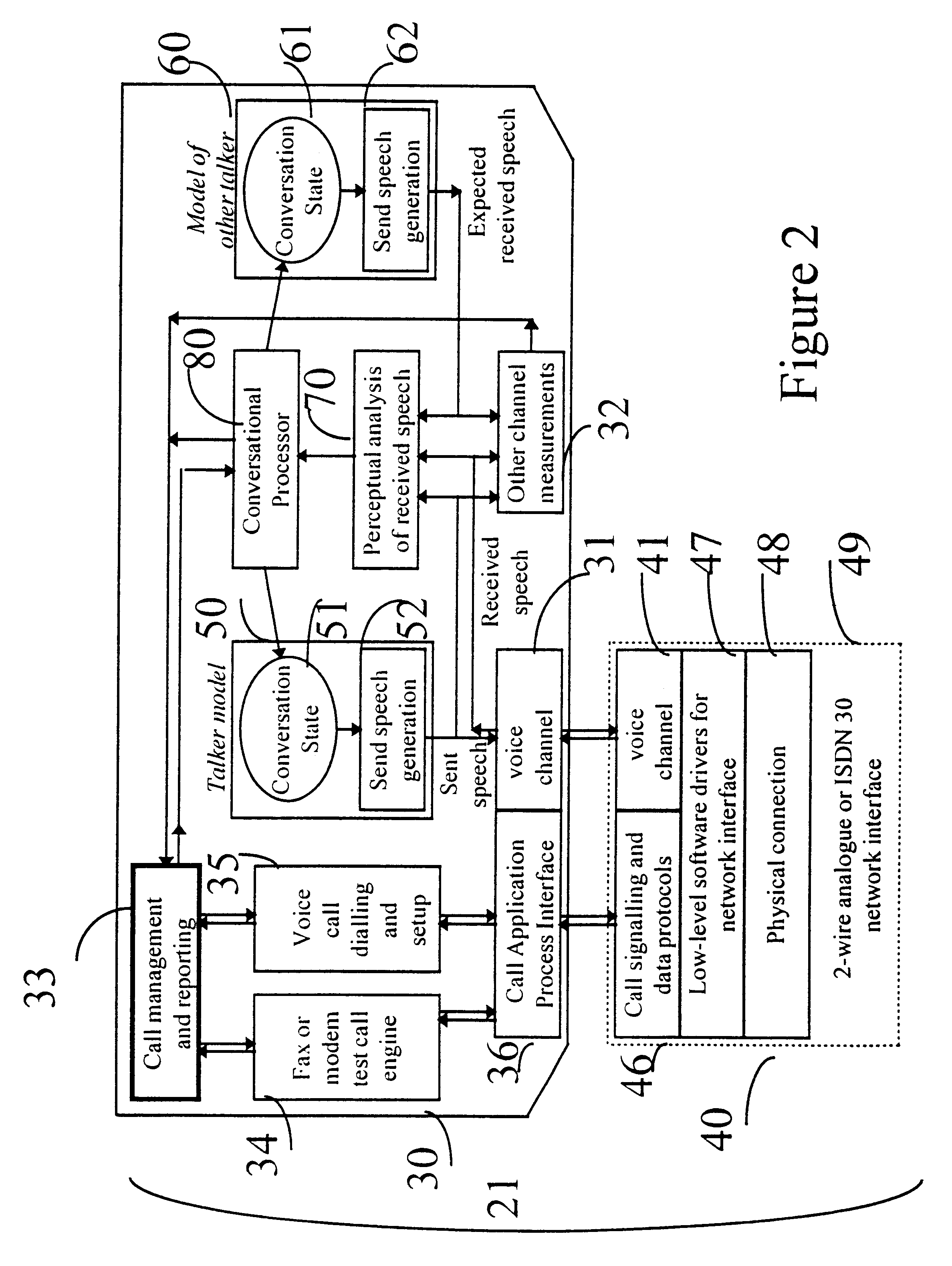
During the call the devices 21, 22 communicate through the network 20 using speech-like signals. The signals sent by each device are governed by a model of the conversation, which determines what is `spoken` based on what has been received and an underlying state encoding the desired content (`conversational intent`) of the call. Quality assessment is performed by at least one device, and preferably by all of them, based on the incomin...


PUM


Abstract

A communications system is tested to simulate a realistic conversation. A first measurement device make a call, through the system it is testing, to a second measurement device and the two devices converse using predetermined speech generated dynamically by each device in response to the signals received from the other, to simulate aspects of conversation over non-perfect communications system link. The progress of the conversation will therefore take different courses according to the quality of the link. For example, if an expected signal is detected by one device, it transmits an appropriate predetermined response to the other device. However, if the expected signal is corrupted, or not received at all, different predetermined responses (or no response at all) are transmitted to the other device. This in turn may cause the other device to repeat the original signal. Because all the responses, including those to poor quality signals, are predetermined, each device can readily determine the quality of the signals received, because each signal received by one device form the other must be one of a limited number of possible responses to the last transmission made by the one device to the other. The devices perform measurements on the sounds they receive from each other, and monitor the progress of the conversation to compute parameters describing aspects of the received signal quality.

Description

1. Field of the InventionThis invention relates to the quality assessment of communications systems.2. Related ArtIn the increasingly liberalised telecommunications market, differentiation by quality is an important factor. The widespread installation of coding equipment in recent years has created the need for a new generation of assessment techniques. Conventional analysis assumes that the system is linear and time-invariant, and characterises it on the basis of delay, frequency response, noise level and noise spectrum. Modern networks exhibit far more complex effects and contain elements such as speech switches and compressive codecs that are highly non-linear and time varying.Two main techniques are used in the industry to characterise the subjective quality of networks and their components. In listening tests a panel of subjects hear a series of sound clips that have been passed through simulated network conditions. Conversational tests require pairs of subjects to communicate ...

Claims


Application Information

Patent Timeline
IPC IPC(8): H04M3/22H04M3/28H04M3/32
CPCH04M3/2236H04M3/323H04M2201/40
Inventor HOLLIER, MICHAEL PREYNOLDS, RICHARD JRIX, ANTONY W
Owner PSYTECHNICS
Why Eureka
Try Eureka