
Sonic emitter with foam stator

a sonic emitter and foam stator technology, applied in the direction of deaf-aid sets, electrical transducers, transducer details, etc., can solve the problem of limited speaker application variation due to lack of substitute compositions

Inactive Publication Date: 2001-10-16
TURTLE BEACH
View PDF40 Cites 33 Cited by
  • Summary
  • Abstract
  • Description
  • Claims
  • Application Information

AI Technical Summary

Benefits of technology

It is an object of the present invention to provide alternate component materials to the generic electrostatic speaker configuration which offer new variations in structural and acoustic properties.
It is a further object of this invention to enable reduction in weight and stiffness requirements by utilizing a foam material as the stator element of the speaker system.
Another object of this invention is to provide an inexpensive foam stator or plate which has little weight and is capable of being formed in a variety of geometric configurations which offer both economy and performance enhancement.
A specific object of the present invention is to provide an electrostatic speaker for audio applications which offers substantial reductions in manufacturing costs and simplified structural design.
In another embodiment of this invention, a push-pull configuration is developed, using a second foam member of similar construction positioned on an opposing side of the electrostatic emitter film from the first foam member. The electrostatic emitter film is sandwiched between the respective foam members and includes a conductive layer in noncontacting relationship with the respective first and second foam members for enabling the film to capacitively respond with the first and second forward faces to the variable voltage in a push-pull relationship.

Problems solved by technology

Although this pattern of material choice has generally served the purposes required for electrostatic speaker, the absence of substitute compositions has limited the variation in speaker applications.
Therefore, weight and geometric configuration become significant design factors.
Furthermore, the requirement for rigidity and the known stiffness of accepted plate materials typically results in construction of the plate element as the load-bearing component of the speaker system.
Taken together, the traditional limitations adopted by this history of plate development has diverted attention from exploring other options for electrostatic speaker design.

Method used


Image

  • Sonic emitter with foam stator
  • Sonic emitter with foam stator
  • Sonic emitter with foam stator

Examples


Embodiment Construction

The preferred embodiments which are disclosed hereafter are provided as illustrations of several inventive concepts which are set forth in the attendant claims. It will be appreciated by those skilled in the art that many variations are possible, and that the drawings and examples provided herein are intended to enable one of ordinary skill in the art to apply these inventive concepts within many different speaker configurations, as well as other devices for propagating sonic energy. Accordingly, it is to be understood that the description that follows is not to be construed as limiting, except as defined in the attendant claims.

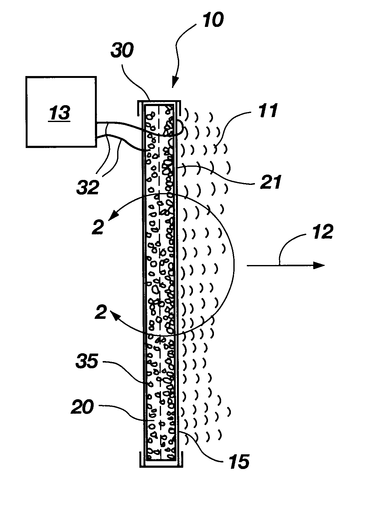
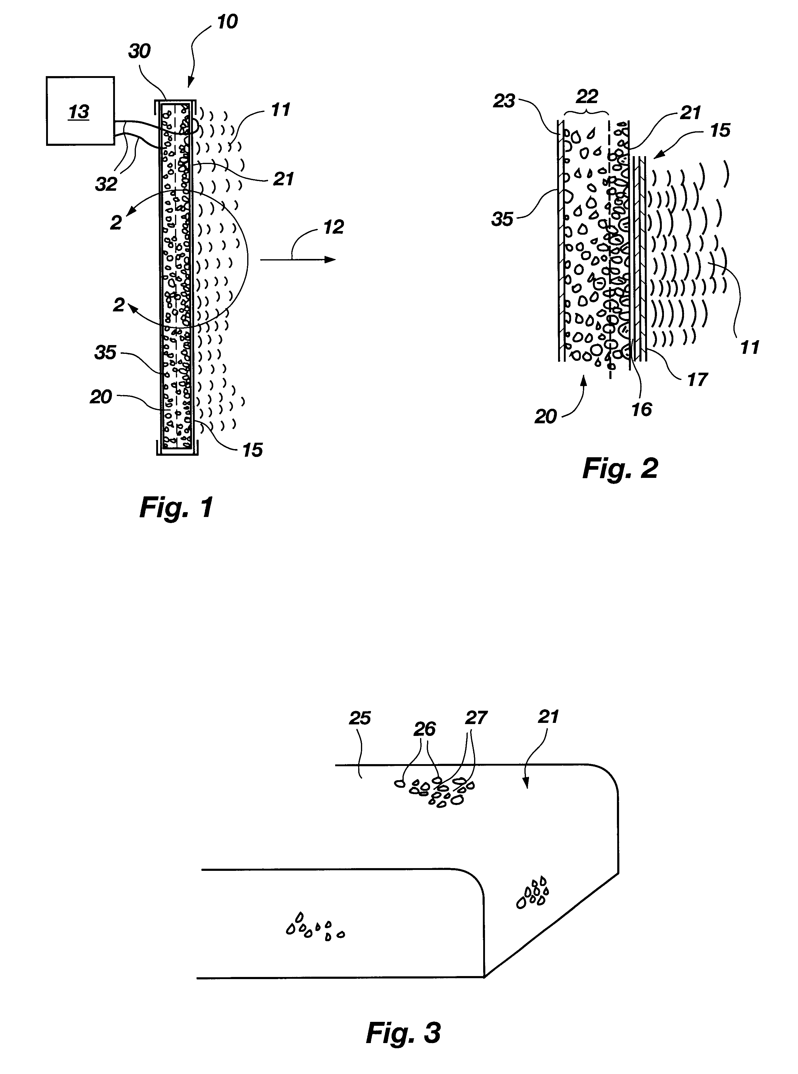
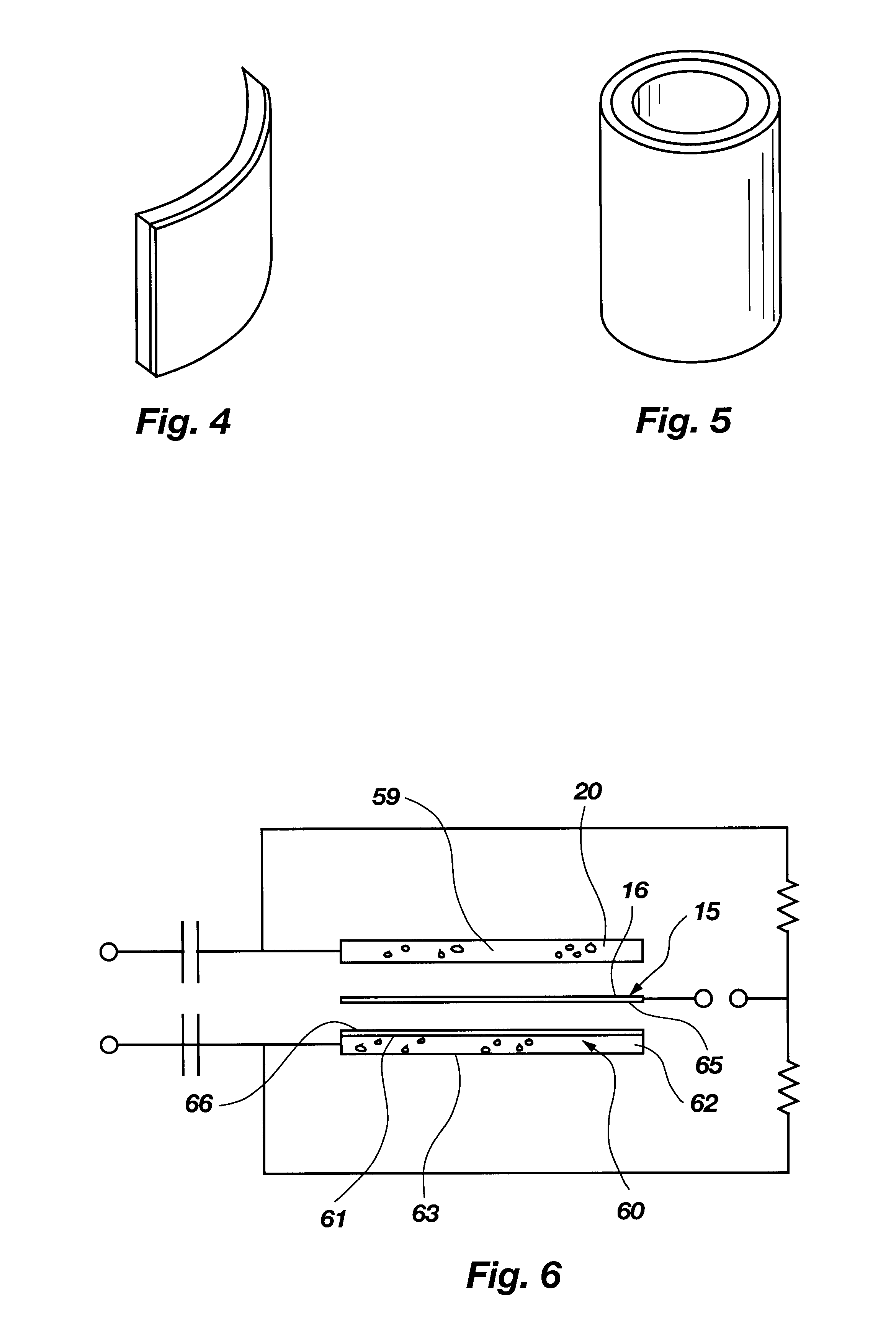
For example, FIGS. 1 and 2 show a single-end speaker device 10 with sonic output 11 being propagated in a forward direction 12. This speaker may be coupled to an audio amplifier or ultrasonic driver 13 which provides the various electronic circuitry support elements for applying a desired sonic signal. Such circuitry is well known and will not be described i...


PUM


Abstract

A speaker device comprising an electrostatic emitter film which is responsive to an applied variable voltage to emit sonic output based on a desired sonic signal, used in combination with at least a first foam member having a forward face, an intermediate core section and a rear face. The forward face is composed of a composition having sufficient stiffness to support the electrostatic film and includes conductive properties which enable application of a variable voltage to supply the desired sonic signal. The surface of the forward face includes small cavities having surrounding wall structure defining each cavity which terminates at contacting edges approximately coincident with the forward face of the foam member. The film is applied to the forward face of the foam member and biased in direct contact with the contacting edges of the forward face.

Description

1. Field of the InventionThe present invention relates to capacitive or electrostatic sonic emitters and more particularly to emitters which include a stator element and associated, movable emitter film useful for generating sonic output as a speaker device in response to an applied variable voltage.2. Prior ArtThe science of acoustics has long known of the utility of a movable electrostatic membrane or film associated with and insulated from a stator or driver member part of as a speaker and / or microphone device. Typical construction of such devices includes a flexible Mylar(tm) or Kapton(tm) film having a metalized coating and an associated conductive, rigid plate which are separated by an air gap or insulative material. An applied voltage including a sonic signal is transmitted to this capacitive assembly and operates to displace the flexible emitter film to propagate the desired sonic compression wave.Two primary categories of electrostatic speakers exists, depending on the appl...

Claims


Application Information

Patent Timeline
Patent Type & Authority Patents(United States)
IPC IPC(8): H04R19/00H04R19/02
CPCH04R19/00H04R3/00
Inventor NORRIS, ELWOOD G.CROFT, III, JAMES J.
Owner TURTLE BEACH
Learn More