
Connecting unit

a technology of connecting unit and connecting shaft, which is applied in the direction of cables for vehicles/pulleys, shafts, brake systems, etc., can solve the problems of considerable cost and considerable amount of work, and achieve the effect of shortening the assembly tim

Inactive Publication Date: 2001-10-23
FICO CABLES
View PDF15 Cites 28 Cited by
  • Summary
  • Abstract
  • Description
  • Claims
  • Application Information

AI Technical Summary

Benefits of technology

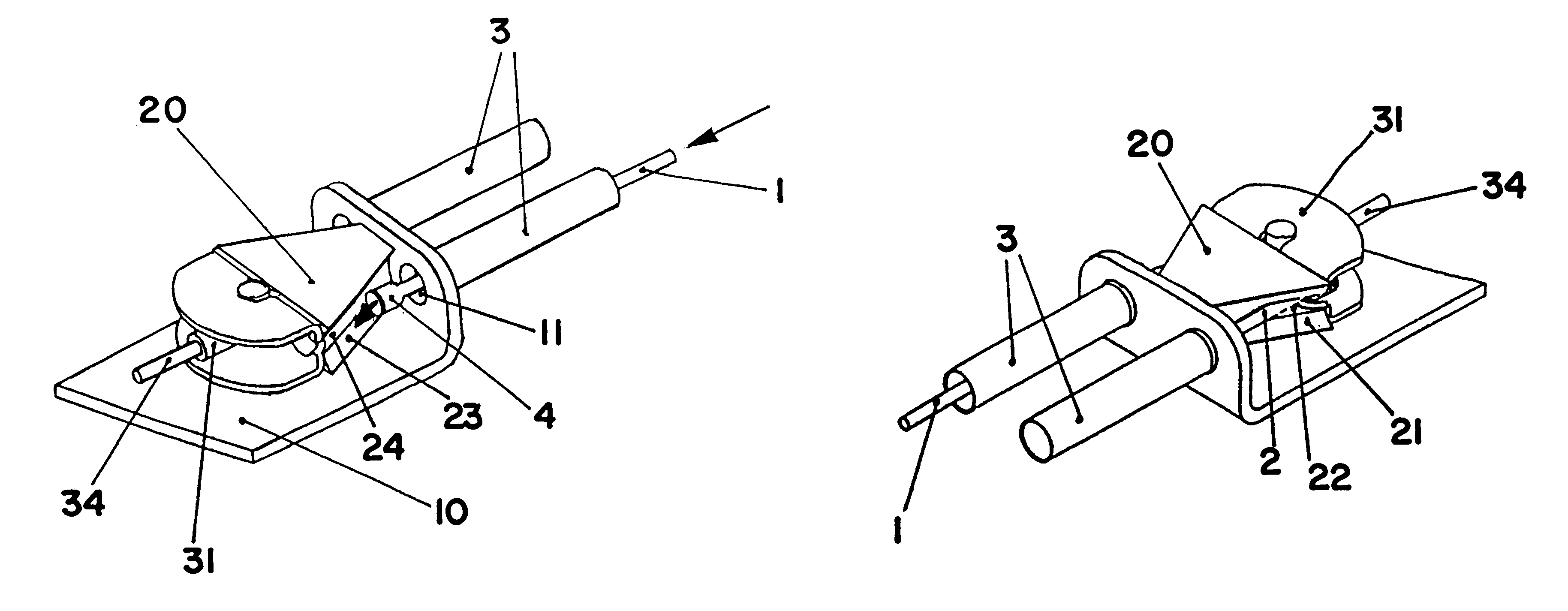
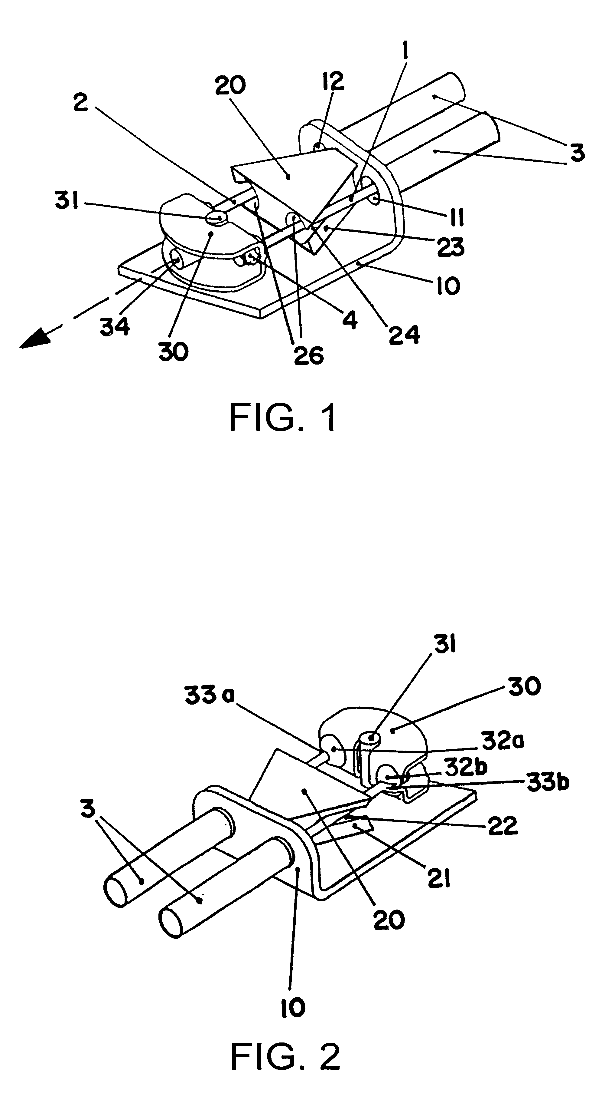
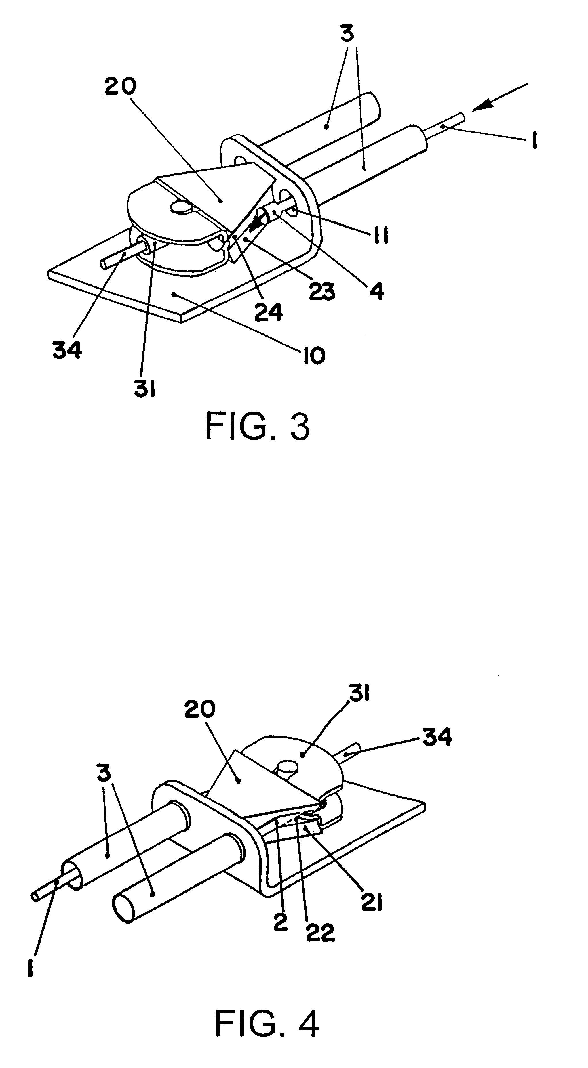
As a result, the bowden cable can "automatically" engage the receptacle in one step by a simple pushing of the end through the opening in the support in the direction of the receptacle. Since the guiding element itself inserts the end of the bowden cable under such a movement into the slit, the complete procedure can be carried out "blind", i.e. without the need to be able to see the connecting unit from the outside. The end of the braking cable in the direction of the receptacle can also be moved by pushing at the other end of the bowden cable so that there is no need to directly access the connecting unit. The complete connecting unit can therefore be arranged inside a closed housing which does not need to be opened for the assembly of the bowden cable. This allows a pre-assembly to a great extent which considerably shortens the time for the assembly of a vehicle at the assembly line.

Problems solved by technology

This kind of connection between receptacle and cable according to the prior art causes during the assembly of bowden cables, in particular in the automotive field a considerable amount of work since the cable has to be manually passed through the small hole in the receptacle before the other end can be connected with the desired part (transmission, brake, etc.).
The overall procedure therefore requires several manual steps and thus causes considerable costs.

Method used


Image

  • Connecting unit
  • Connecting unit
  • Connecting unit

Examples


Embodiment Construction

The particularly preferred embodiment of the invention described in the following is used as a part of a parking brake system of a vehicle.

However, it has to be understood that the invention can be used wherever a pulling movement is to be transmitted to one or several bowden cables.

With reference to FIG. 1 the connecting unit comprises a support 10 having a horizontal and vertical section (cf. FIG. 6). The support serves preferably for mounting the connecting unit to the vehicle. To this end several further (not shown) borings can be provided for mounting screws or the like. Conceivable is also to glue the support to the frame of the vehicle.

As a protection against dirt and / or corrosion the complete connecting unit can be arranged inside a housing (not shown) having on its one side an opening for the cable 34 and on the other side two openings for the two cables 1, 2. If needed, the support 10 can be an integral part of the housing.

In the vertical section of the support preferably ...


PUM


Abstract

The present invention relates to a connecting unit for the transmission of pulling movements to one end of at least one bowden cable, in particular for a parking brake of a vehicle. The present invention further relates to a method for establishing a connection between a bowden cable and a pulling element for the transmission of pulling movements, as it is preferably used during the assembly of parking brakes in vehicles.The connecting unit comprises a support with at least one opening for the mounting of the connecting unit, a pulling element with at least one receptacle for the end of the at least one bowden cable and a guiding element, where the end of the at least one bowden cable can engage the receptacle, and the guiding element is arranged between the at least one opening of the support and the at least one receptacle. The guiding element deflects the end of the at least one bowden cable under a movement in direction of the receptacle through the at least one opening of the support to the side to engage the receptacle.

Description

1. TECHNICAL FIELDThe present invention relates to a connecting unit for the transmitting of pulling movements to at least one bowden cable, in particular for a parking brake of a vehicle. The present invention further relates to a method for establishing a connection between a bowden cable and a pulling element for the transmitting of pulling movements, as it is preferably used during the assembly of parking brakes in vehicles.2. THE PRIOR ARTBowden cables serve in many fields of technology for transmitting movements from one place to another. In motor vehicles for example the transmission is often controlled by a shift lever whose movements are transmitted by means of one or more bowden cables. A further typical field of use for bowden cables is the parking brake of a car. In this case the movement of a lever is transmitted by two bowden cables to the brakes usually mounted to the two rear wheels to achieve a simultaneous operation of the two brakes.For transmitting the pulling mo...

Claims


Application Information

Patent Timeline
IPC IPC(8): B60T11/04B60T11/06B60T11/00F16C1/14F16C1/10
CPCB60T11/04B60T11/06F16C1/14Y10T403/1616Y10T74/20462
Inventor GABAS, CARLOS
Owner FICO CABLES
Learn More