Intake manifold with internal fuel rail and injectors

a technology of injectors and intake manifolds, which is applied in the direction of liquid fuel feeders, machines/engines, combustion air/fuel air treatment, etc., can solve the problems of unwanted vibration, difficult and time-consuming assembly process, and noisy injectors

Inactive Publication Date: 2001-10-30
SIEMENS CANADA LTD +1
View PDF22 Cites 57 Cited by
  • Summary
  • Abstract
  • Description
  • Claims
  • Application Information

AI Technical Summary

Problems solved by technology

This mounting arrangement requires special seals and the assembly process can be difficult and time consuming.
Further, since the fuel injectors are mounted outside of the manifold, the injector

Method used


Image

  • Intake manifold with internal fuel rail and injectors
  • Intake manifold with internal fuel rail and injectors
  • Intake manifold with internal fuel rail and injectors

Examples


Embodiment Construction

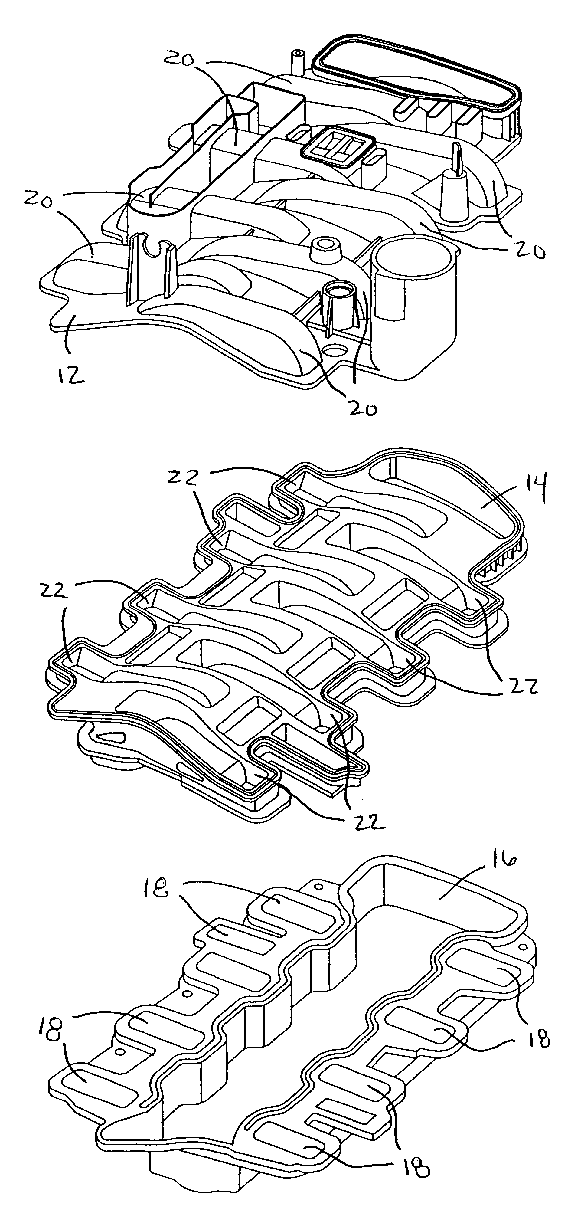
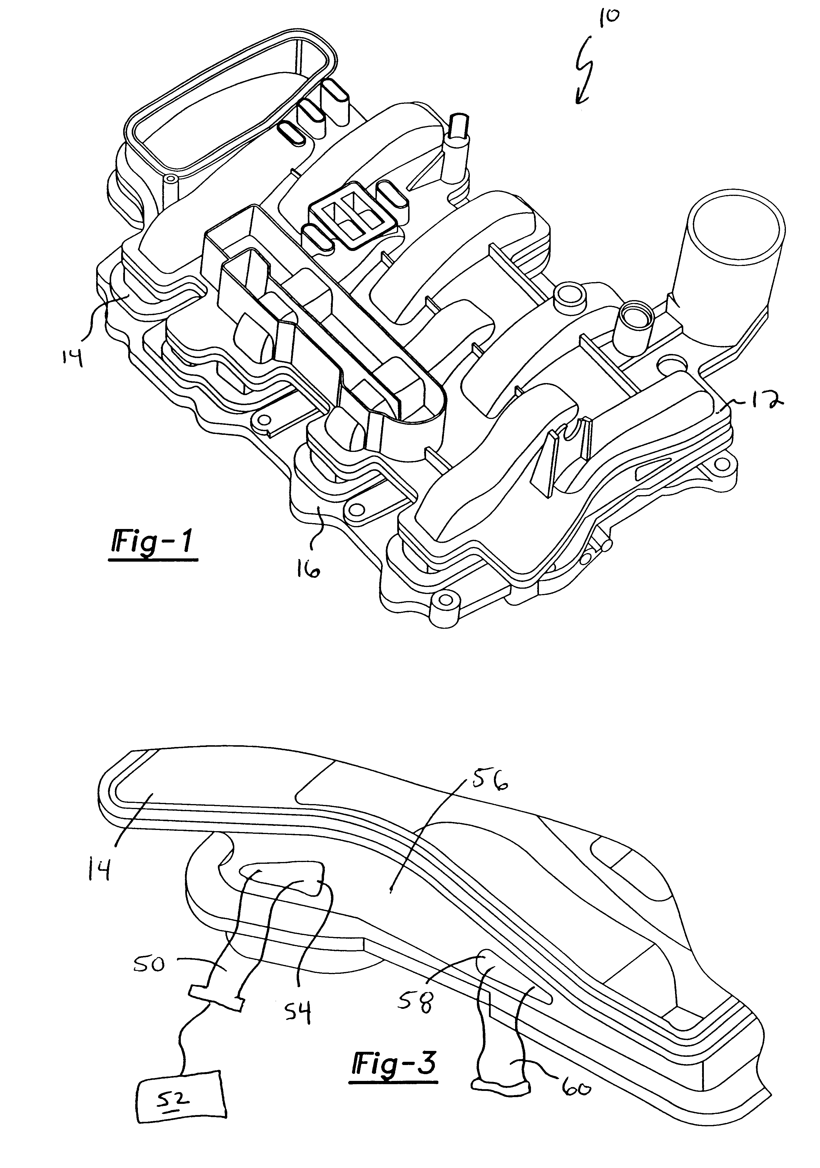
An intake manifold is shown generally at 10 in FIG. 1. The intake manifold 10 is mounted to an internal combustion engine (not shown) to supply air for combination with fuel to form a combustible mixture used to power the engine. The intake manifold includes an upper shell 12, a middle shell 14, and a lower shell 16. The middle shell 14 is sandwiched between the upper 12 and lower 16 shells during assembly to provide a sealed assembly.

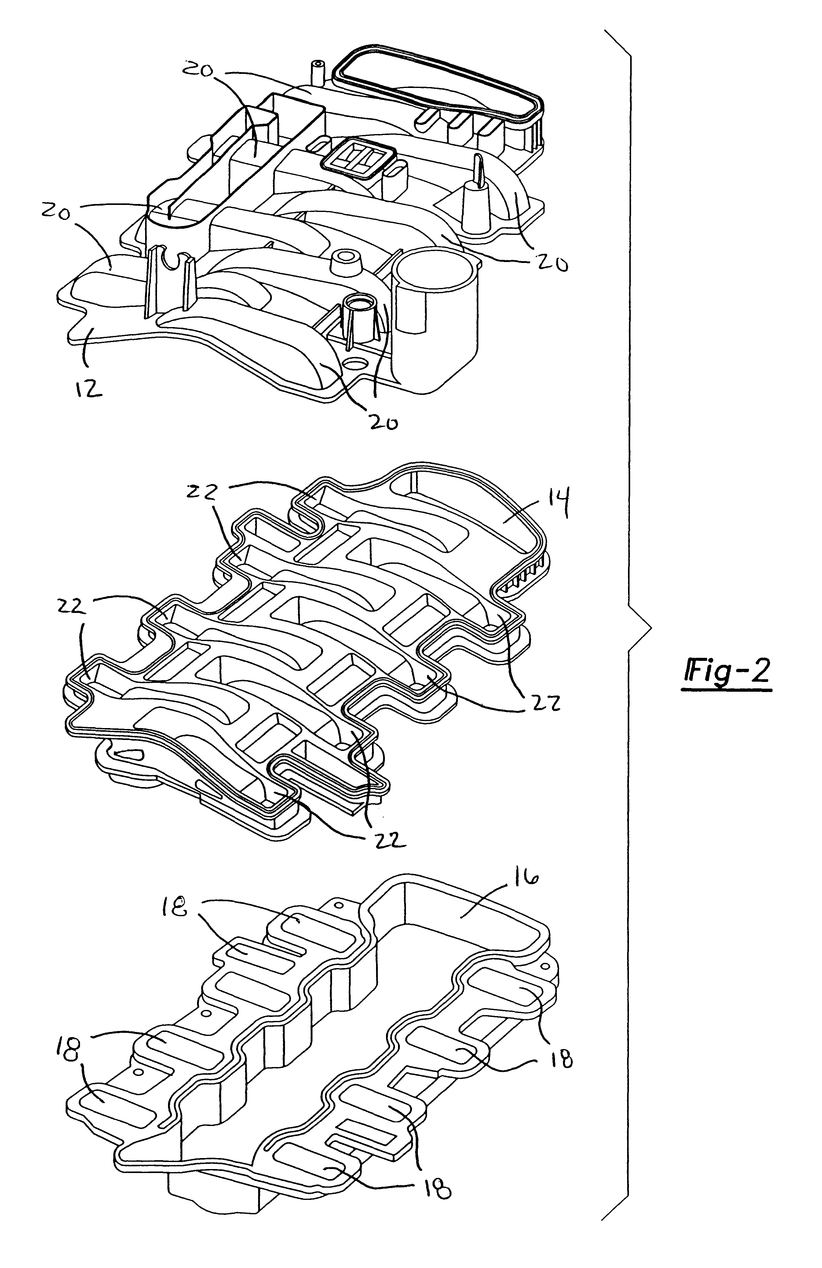
As shown in FIG. 2, the lower shell 16 includes a plurality of longitudinally spaced shell ports 18. Each of the ports 18 is adapted for installation over a corresponding intake port for the engine. The upper shell 12 includes a plurality of runners 20 that are used to guide air to the shell ports 18 as is known in the art. The middle shell 14 is installed between the lower 16 and upper 12 shells and includes a plurality of channels 22 that interconnect the runners 20 and the shell ports 18.

Once the shells 12, 14, 16 are assembled together, a plurality...


PUM


Abstract

An intake manifold includes an upper shell, a lower shell, and a middle shell that interconnects the upper and lower shells. The lower shell has a plurality of longitudinally spaced shell ports. Each shell port is adapted for installation over a corresponding intake port for an engine cylinder head. The upper shell has a plurality of runners that are used to guide air to the shell ports. The middle shell has a plurality of channels that interconnect the runners and the shell ports such that air can flow through the runner to the cylinder intake port. Fuel injector pockets are formed within the upper, middle, and lower shells with each of the pockets having an injector opening in communication with the corresponding shell port. An internal fuel rail, formed between the upper and middle shells, supplies fuel to each of the injector pockets. A fuel injector is installed into each injector pocket such that the injectors are substantially enclosed within the manifold. An internal wire harness rail, formed between the upper and middle shells, supports a wire harness that electrically connects each of the injectors to a power supply.

Description

1. Field of the InventionThis invention relates to an air intake manifold and method for assembly thereof where the intake manifold includes an internal fuel rail and wire harness that allows fuel injectors to be installed inside the manifold to form a subassembly.2. Related ArtInternal combustion engines operate by burning a mixture of fuel and air in a cylinder containing a piston. Engine power is provided by a continuous cycle that takes place inside the engine. First, as the piston moves downward, an inlet valve opens and a mixture of fuel and air is sucked into the cylinder chamber. The valve closes and the piston moves up to compress the mixture. An electric spark plug produces a spark that ignites the fuel, forcing the piston back down. Finally, an outlet valve opens and the piston rises back up to release the exhaust gases out of the cylinder. The cycle continually repeats itself until the engine is shut down.The engines use fuel injectors to control injection of fuel into t...

Claims


Application Information

Patent Timeline
IPC IPC(8): F02M63/00F02M63/02F02M69/46F02M35/104F02M51/00F02M35/10
CPCF02M35/10039F02M35/10045F02M35/10052F02M35/10072F02M35/10111F02M35/10144F02M35/10216F02M35/10262F02M35/10288F02M35/10321F02M35/10347F02M35/1036F02M35/116F02M51/005F02M63/0225F02M69/465Y02T10/146Y02T10/12
Inventor MAMMARELLA, JOHN R.MARENTETTE, JOHN F.WORREL, CHRISTINE C.KENNEDY, GARY I.
Owner SIEMENS CANADA LTD
Why Eureka
Try Eureka