Dual mode eraser

a technology of eraser and eraser, which is applied in the field of detection systems for transcription, can solve the problems of large, cumbersome, expensive, and immobile whiteboard systems, and the use of passive electronic boards

Inactive Publication Date: 2001-10-30
SANFORD LP
View PDF106 Cites 98 Cited by
  • Summary
  • Abstract
  • Description
  • Claims
  • Application Information

AI Technical Summary

Benefits of technology

Further according to this embodiment, the stylus and / or the writing element may include electronics which causes a signal to be transmitted by the stylus which identifies the stylus and / or the writing element as being compatible with the transcription system. In this regard, the stylus and / or the writing element may include logic for producing encoded identification signals, the transcription system also including logic for recognizing the encoded identification signals. By incorporating this feature, use of styluses and writing elements incompatible with the transcription system can be prevented by the system.
Further, the first and second detectors 12A, 12B are disclosed as being removable from a writing surface 28. However, the first and second detectors 12A, 12B can also be integrated with the writing surface 28. In embodiments where the first and second detector 12A, 12B are integrated with the writing surface 28, the calibration acts described above can be eliminated since the writing area 38 dimensions will be constants which can be administratively entered into the system before the system is sold to the end consumer. Additionally, although the system is disclosed with first and second detectors 12A, 12B, additional detectors may be added to the system to facilitate the calibration process, to provide additional resolution to the monitor image 34 or the further refine the monitor image 34.

Problems solved by technology

The passive electronic boards tend to use large, expensive, board-sized photocopying mechanisms.
Typical whiteboard systems are large, cumbersome, expensive and immobile.

Method used


Image

  • Dual mode eraser
  • Dual mode eraser
  • Dual mode eraser

Examples


Embodiment Construction

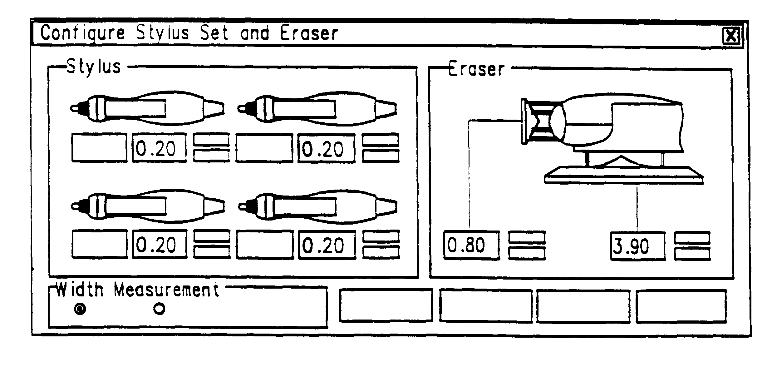
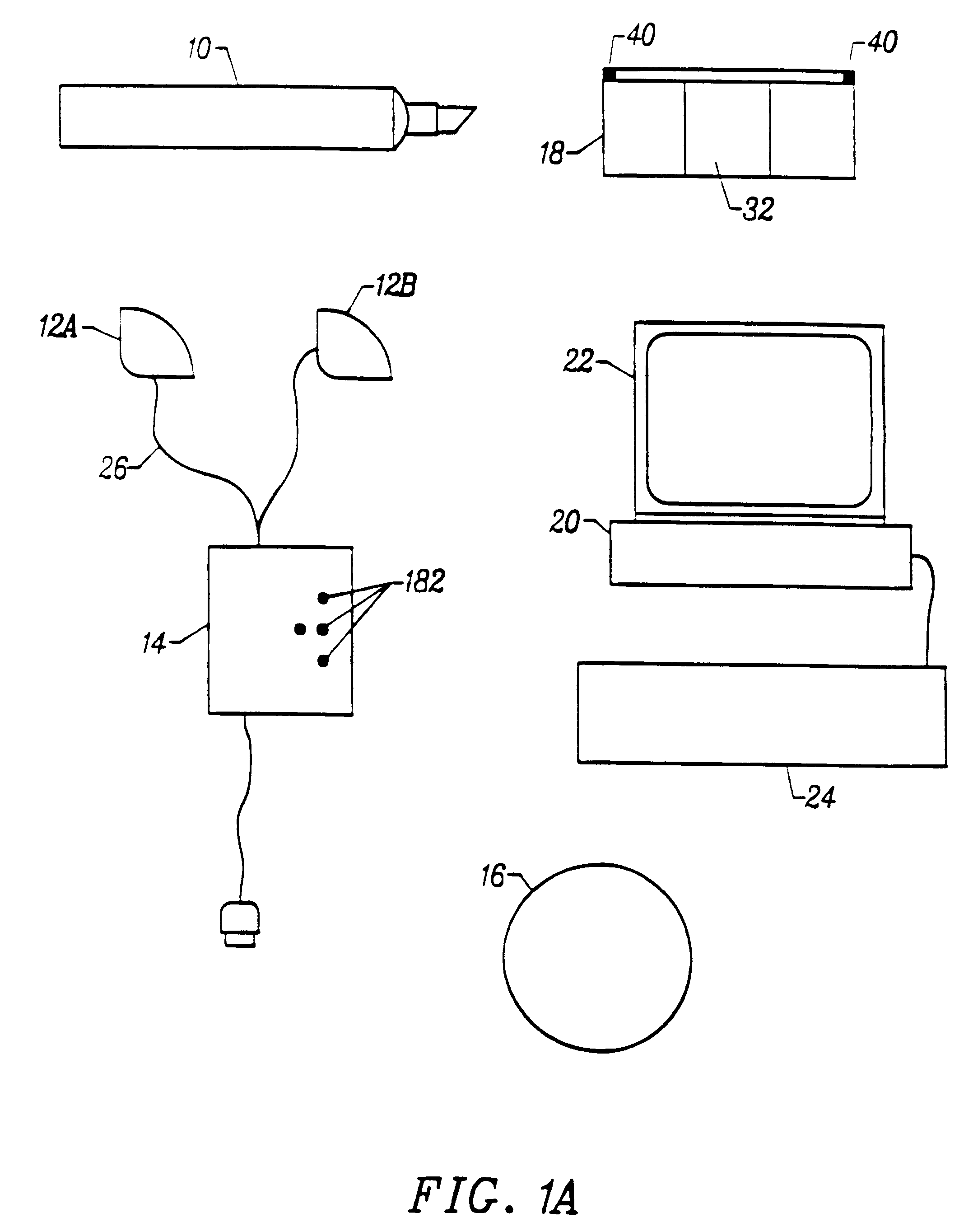
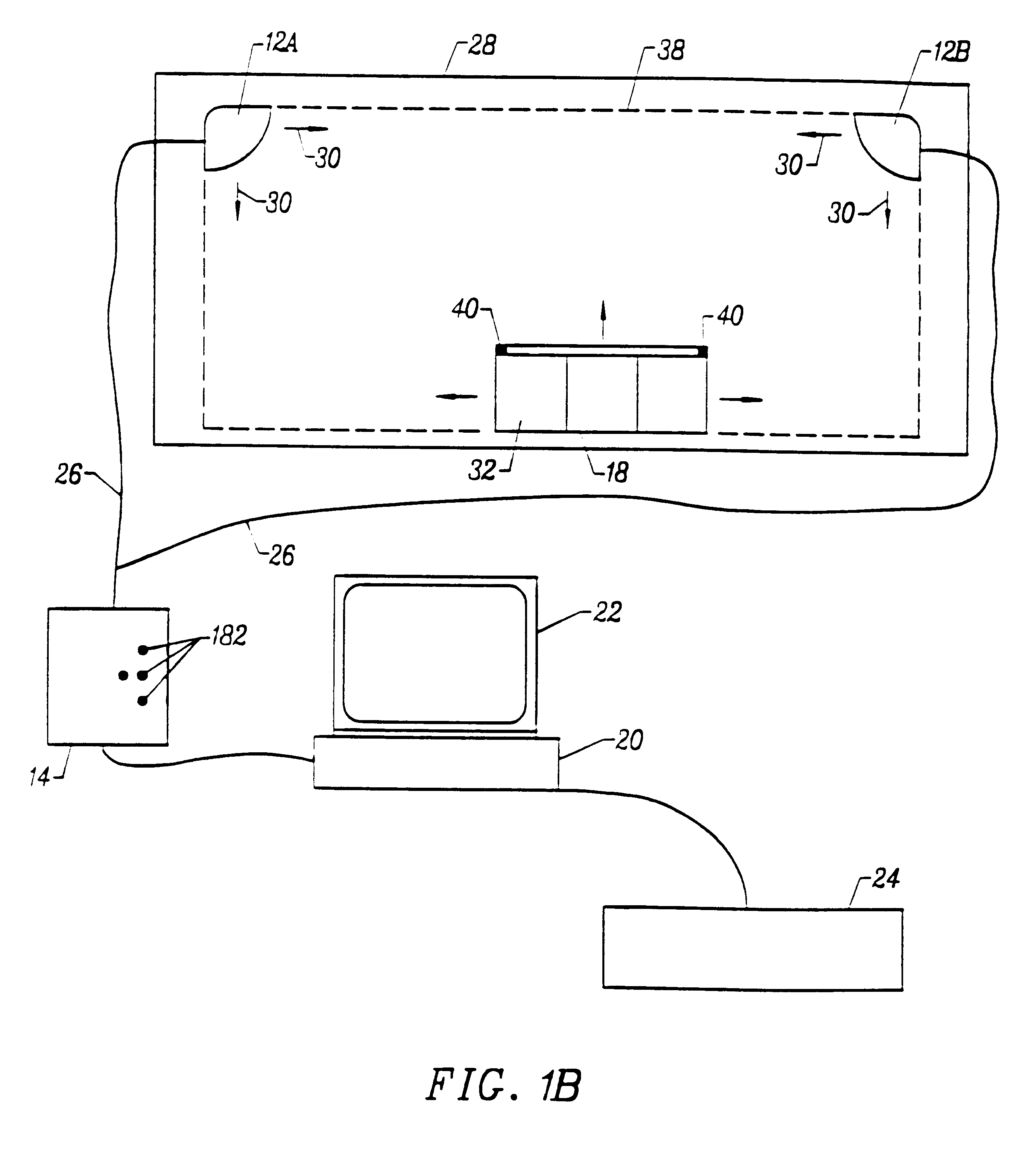
The following is an example of a transcription system according to the present invention, its contents and operation. FIG. 21 illustrates a transcription system kit. As illustrated, the kit includes a detector assembly 512, a set of styluses 514, a set of whiteboard markers 516, an eraser 518, and a template 520.

FIG. 22 illustrates a stylus 514 which has been taken apart so that a marker 516 can be placed within the stylus 514. As illustrated, the stylus 514 includes a stylus body 522 which houses a AAA battery 524 and an ultrasound transmitter 526 adjacent a writing end 528 of the stylus. The stylus 514 also includes a side cover 530 which is sufficiently clear or translucent such that one can see the marker 516 through the side cover 530. The stylus 514 also includes a cap 532 which is sufficiently clear or translucent such that one can see a writing tip of the marker 516 through the cap 532.

FIGS. 23A and 23B illustrate a stylus 514 containing a marker 516.

FIG. 23A illustrates a s...


PUM


Abstract

A method and apparatus for transcribing composite images. In one embodiment, a method comprises projecting a first image onto a surface, wherein a first coordinate system defines positions within the first image and a second coordinate system defines positions on the surface. The method further comprises forming a second image on the surface by using a stylus, and recording the formation of the second image relative to the first image by periodically detecting the position of the stylus relative to the second coordinate system by receiving and processing signals transmitted from the stylus. The method also comprises translating the position of the stylus relative to the second coordinate system to a position relative to the first coordinate system, and storing the composite image comprising the first image and the second image as machine-readable data.

Description

The invention is in the field of recording writing performed on a surface and, more particularly in the field of recording a composite of the writing performed on the surface and a preexisting image.Technologies for capturing and storing handwritten notes include digitized writing surfaces such as electronic whiteboards or SMARTBOARDS.TM.. These electronic whiteboards typically either photocopy an entire writing surface or serve as the actual input device (e.g. an electronic template) for capturing the handwritten data. The whiteboards may be active or passive electronic devices with a surface on which the user writes with a special stylus. The active devices may be touch sensitive, or responsive to a light or laser pen wherein the whiteboard includes a detector that detects the active signal. The passive electronic boards tend to use large, expensive, board-sized photocopying mechanisms.Typical whiteboard systems are large, cumbersome, expensive and immobile.SUMMARY OF THE DISCLOSU...

Claims


Application Information

Patent Timeline
Patent Type & Authority Patents(United States)
IPC IPC(8): G06F3/033G06F3/041G06F3/043
CPCG06F3/03545G06F3/0418G06F3/043G06F3/0433
Inventor DAVIS, RICHARD C.CHERY, YONALDKELLEY, III, ANDREWMOYNE, WILLIAM P.VERMINSKI, MATTHEW D.
Owner SANFORD LP
Why Eureka
Try Eureka