Electrical rechargeable battery in the form of a button cell

a technology of electric rechargeable batteries and button cells, which is applied in the direction of flat cell groups, nickel accumulators, cell components, etc., to achieve the effect of increasing electrical power and producing economically

Inactive Publication Date: 2001-11-06
VARTA MICROBATTERY
View PDF6 Cites 47 Cited by
  • Summary
  • Abstract
  • Description
  • Claims
  • Application Information

AI Technical Summary

Benefits of technology

It is accordingly one object of the invention to produce an electrical rechargeable battery in the form of a button cell, which has increased electrical power and to this extent can be compared with comparable round cells and prismatic cells, but which furthermore can be produced economically in a manner which is suitable for automation.

Problems solved by technology

They, therefore, do not replace conventional round cells, which allow very much greater discharge currents.

Method used


Image

  • Electrical rechargeable battery in the form of a button cell
  • Electrical rechargeable battery in the form of a button cell
  • Electrical rechargeable battery in the form of a button cell

Examples


Embodiment Construction

and the appended claims.

The subject matter of the invention will be explained in more detail in the following text with reference to FIGS. 1 to 8.

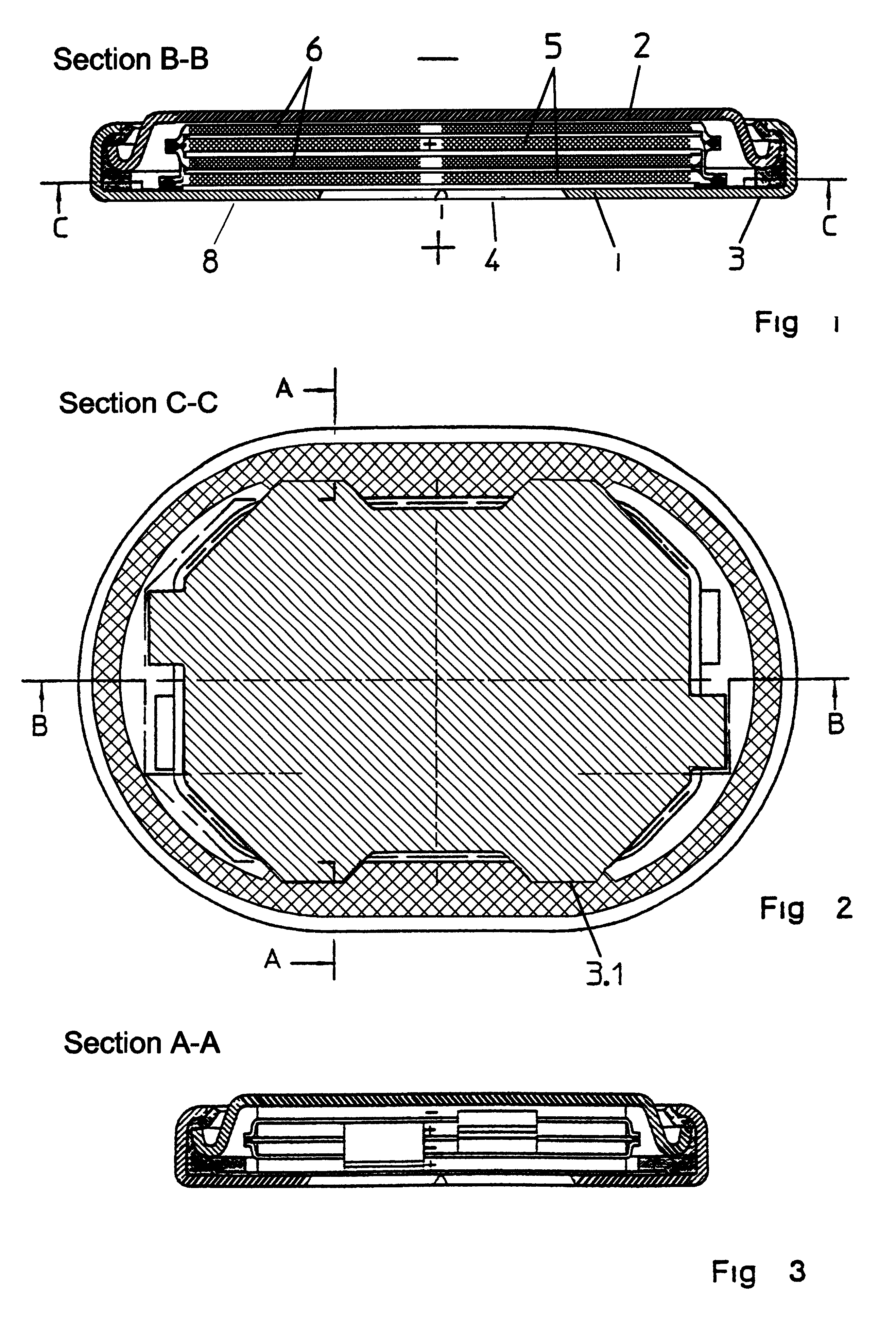
FIG. 1 shows a cross section taken through a button cell according to the invention, along the line B--B in FIG. 2.

FIG. 2 is a top plane view of one embodiment of a button cell in accordance with aspects of the invention.

FIG. 3 shows a section along the line A--A in FIG. 2.

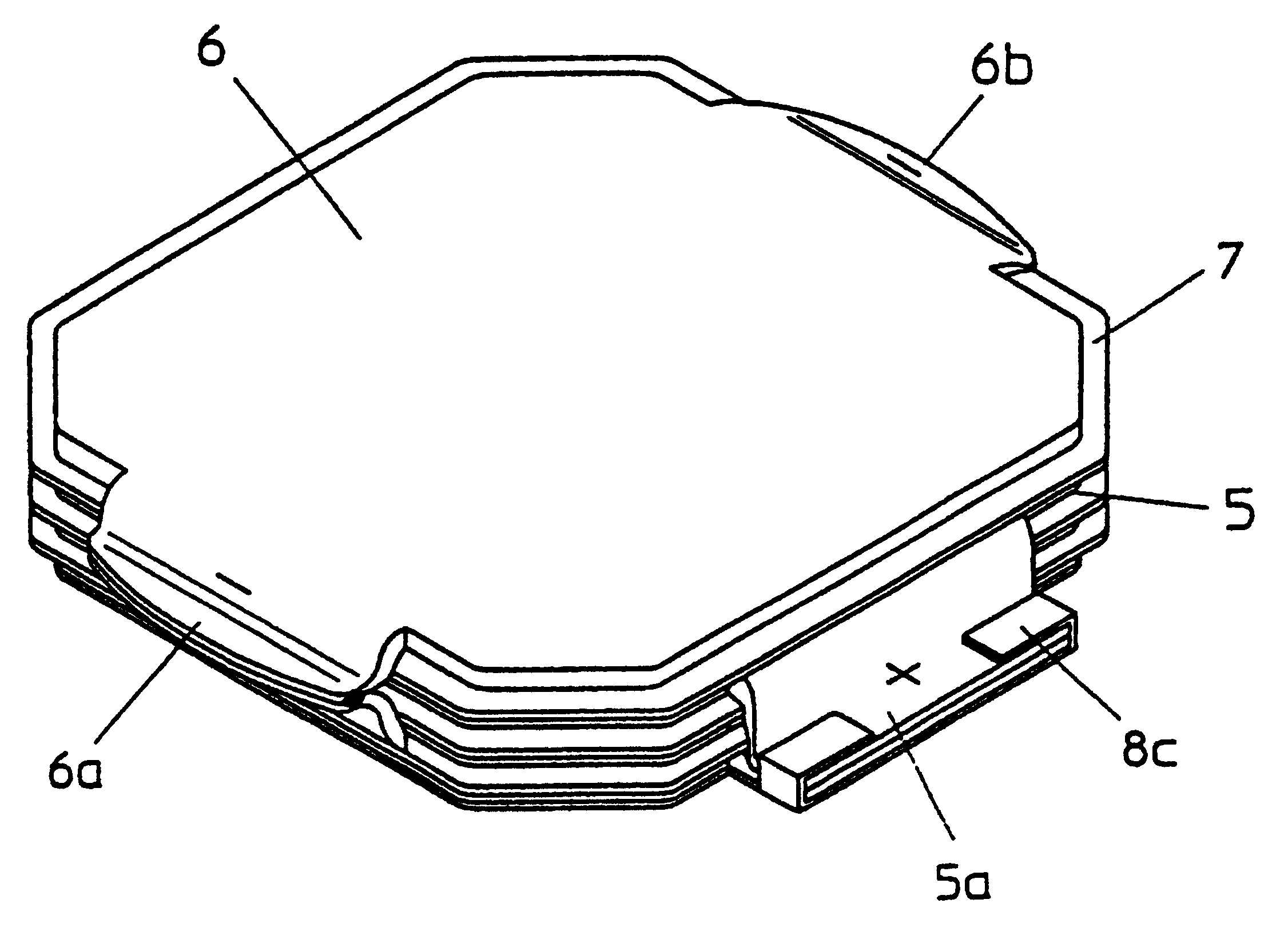
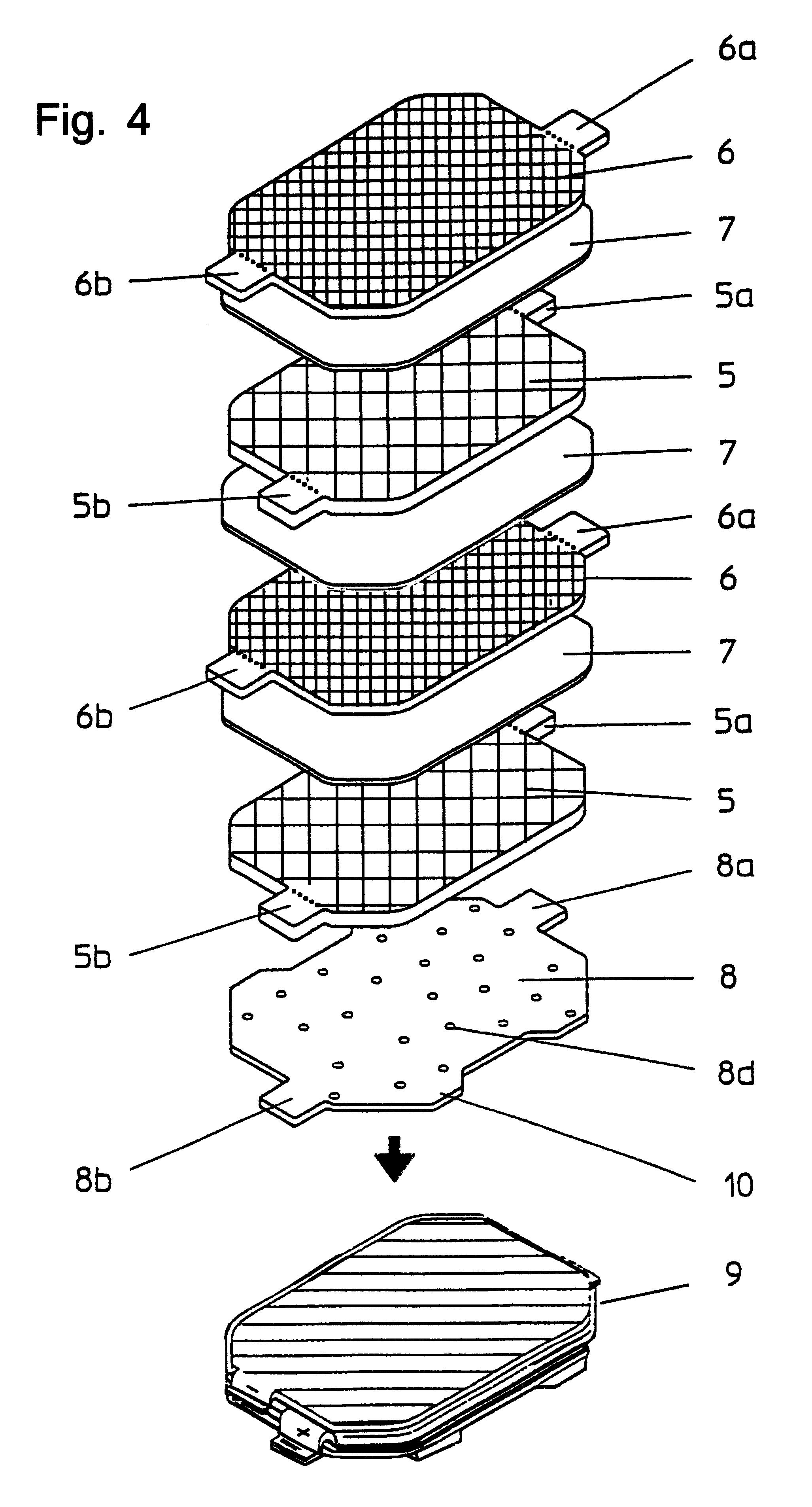
FIG. 4 shows a perspective view of the basic construction of the electrode set in this cell, broken into individual pieces for case of understanding.

FIG. 5 shows a perspective view of one possible configuration of a contact plate which is used in accordance with aspects of the invention.

FIG. 6 shows a top plane view of a cylindrical button cell in accordance with aspects of the invention.

FIGS. 7 and 8 show perspective views of electrode packets in accordance with aspects of the invention.

The following description is intended to refer to specific embodiments of the invent...


PUM

PropertyMeasurementUnit
polarityaaaaaaaaaa
circumferencesaaaaaaaaaa
conductiveaaaaaaaaaa

Abstract

An electrical accumulator having a case in the form of a button cell which is closed such that it is gastight, including a case cover and a case cup with an interposed electrically insulating seal, which contain an electrode set including positive and negative electrodes as well as interposed separators, with at least two electrodes of one polarity being mechanically. and electrically connected at at least two points on their circumference in such a manner that a mechanically robust electrode packet results. The invention furthermore relates to a method for producing such a rechargeable battery.

Description

This invention relates to an electrical rechargeable battery having a case in the form of a button cell which is closed such that it is gastight. The invention also relates to a method for producing the rechargeable battery.Button cells generally have a flat-cylindrical or oval gastight case in which, if required, a plurality of positive and a plurality of negative electrodes with interposed separators as well as an electrolyte are arranged one above the other. The button cell itself comprises a case cup and a case cover, between which an electrically insulating plastic seal is arranged. Normally, the case cup polarity is positive and the case cover polarity is negative. The electrodes in many conventional button cells are so-called "mass electrodes" in the form of compressed powder tablets, which are held in a fine-mesh pure nickel wire mesh. It is also known for nickel-foam pure electrodes in the form of paste to be used as the basic material, from which the button cell electrodes...

Claims


Application Information

Patent Timeline
Patent Type & Authority Patents(United States)
IPC IPC(8): H01M2/26H01M2/02H01M10/34H01M4/80H01M6/12H01M4/64H01M6/46H01M10/04H01M10/30H01M50/54
CPCH01M2/266H01M2/0222H01M10/34Y10T29/49108Y02E60/124Y10T29/4911H01M10/345Y02E60/10Y02P70/50H01M50/109H01M50/54
Inventor KILB, MANFREDILIC, DEJANPYTLIK, EDUARDWEITBRECHT, SIEGFRIED
Owner VARTA MICROBATTERY
Why Eureka
Try Eureka