Eureka AIR delivers breakthrough ideas for toughest innovation challenges, trusted by R&D personnel around the world.

Routing in a communications network

Inactive Publication Date: 2001-11-06
BRITISH TELECOMM PLC
View PDF10 Cites 23 Cited by
  • Summary
  • Abstract
  • Description
  • Claims
  • Application Information

AI Technical Summary

Problems solved by technology

A known disadvantage of this type of network is that the behaviour of the network under certain critical conditions can become unpredictable and even chaotic, possibly resulting in catastrophic failure of an entire communications network for a period of time.
The network is difficult to simulate because the degree of complexity embodied by large numbers of distributed nodes taking part in dynamic routing can only be approximated roughly by a mathematical model.
A further disadvantage of this type of network is that a large proportion of the nodes within a communications network have to conform to a particular specification, i.e. hardware and software must precisely match the requirements for a particular type of node, and thus the phased introduction of this type of network is more difficult than the phased introduction of communications nodes which are monitored by one or several central network monitoring sites.
This results in a large degree of co-ordination and administration during the evaluation and design of the route.
Furthermore, as there may be a number of different possible ways of providing a route between a given pair of customer sites, problems may arise when dealing with different company divisions along the route which may feel the need to compete against each other.
When seen within the context of the overall route, however, what may have been an advantage at a local level may turn out to be a disadvantage within the route as a whole.
Due to the cost of the administrative design process, it may not be cost efficient to perform an additional iteration of the design process, resulting in the provision of a route that is more expensive than that which may have theoretically been achieved.

Method used


Image

  • Routing in a communications network
  • Routing in a communications network
  • Routing in a communications network

Examples


Embodiment Construction

It should be noted that "telecommunications networks" may be referred to in this specification but that the invention should not be considered to be limited to any particular type of communications network by that terminology, such as networks which only connect telephones, but extends to other types of network perhaps carrying data between data processing points for instance.

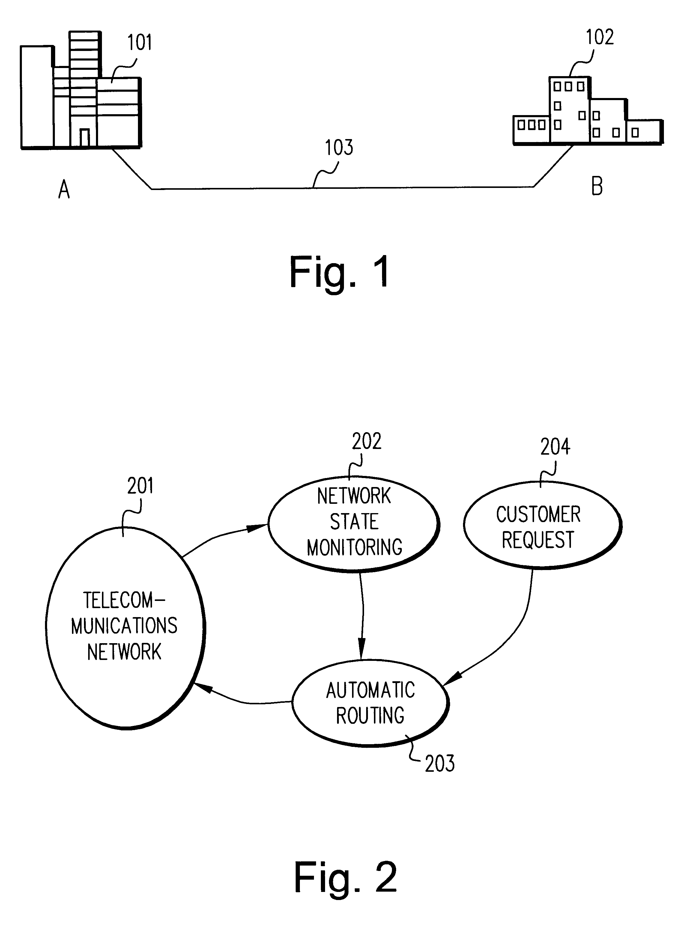
A hypothetical connection is shown in FIG. 1 between two offices of a company at different geographical locations. An office 101 at geographical location A is connected to an office 102 at geographical location B via a telecommunications link 103, which is provided by a telecommunications provider. Thus FIG. 1 shows a typical example in which a customer requires a permanent route for a telecommunications channel to be set up on its behalf by a telecommunications provider.

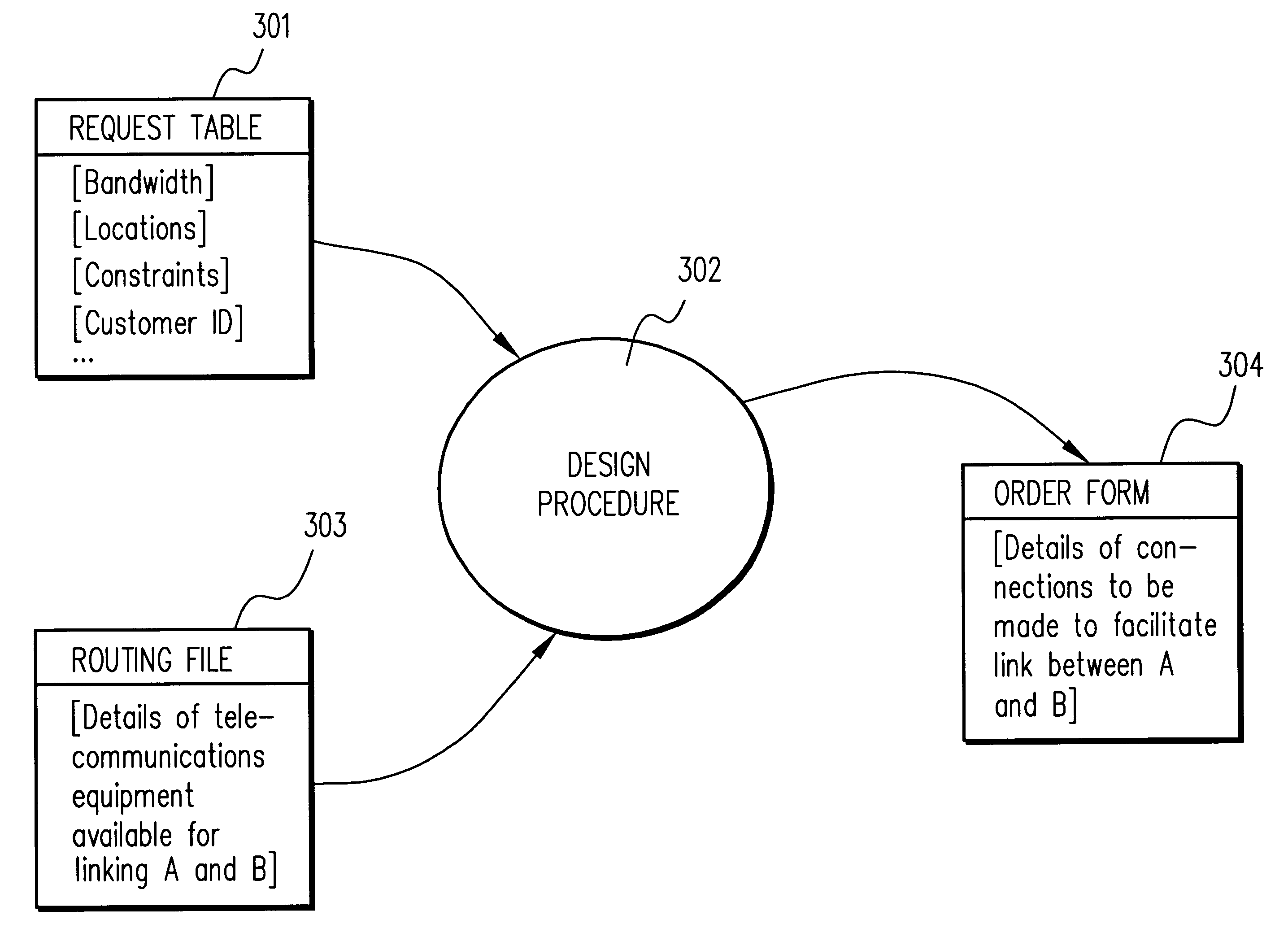
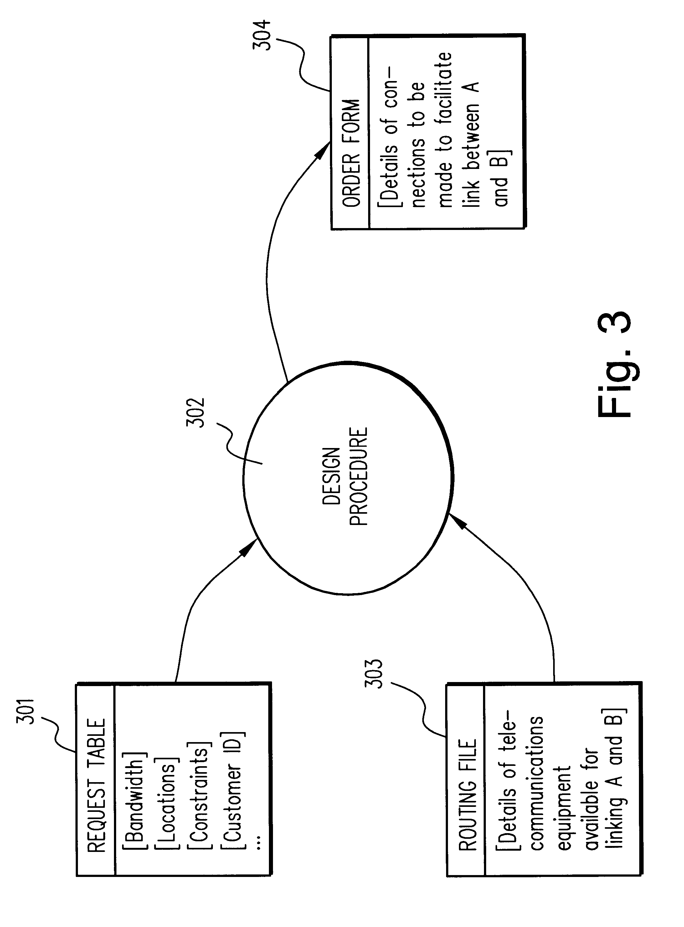
Once a user, in this case a company with sites at locations A and B, requests a link of this type to be set up, the telecommunications provide...


PUM


Abstract

A path between a selected first node and a selected second node is identified in a telecommunications network. A system cost is estimated for making a connection between the first node and the second node, a potential first intermediate note interconnectable from the first node is identified and a first set of systems costs are estimated from said first intermediate nodes to said second node. In addition, the second intermediate nodes connectable from the second node are identified and a second set of systems costs are estimated from the second intermediate nodes to the first node. On the basis of a comparison between the first set of systems costs and the second set of systems costs, between the first and second nodes, a starting node and a target node are selected.

Description

The present invention relates to identifying a path between a selected first node and a selected second node in a communications network to provide routing in the network.RELATED ARTOver recent years communications companies have increasingly provided their customers with an improved quality of service and an improved range of services due to the introduction of digital communications equipment. Thus the equipment that is found within network interconnection sites (trunk exchanges) and local service exchanges is largely digital. However, the connection between local service exchanges and network interconnection sites may consist of a variety of different technologies including copper coaxial cable, fibre optic cable, radio links and satellite links.In order to take advantage of changing demands placed on a communications network, for example the changes in communications traffic density that occur throughout a daily cycle, digital communications equipment may be controlled to divert...

Claims


Application Information

Patent Timeline
IPC IPC(8): H04L12/56H04M3/00H04L12/701H04L12/721
CPCH04L45/00H04L45/44
Inventor REEVE, STEPHEN
Owner BRITISH TELECOMM PLC
Why Eureka
Eureka Blog
Learn More