
Systems and methods for post-processing decompressed images

a post-processing and image technology, applied in the field of systems and methods for post-processing decompressed images, can solve the problems of loss of image information, coarser quantization the greater the loss, and the introduction of quantization errors can become particularly apparent and even objectionabl

Inactive Publication Date: 2001-11-13
ARRIS ENTERPRISES LLC
View PDF9 Cites 154 Cited by
  • Summary
  • Abstract
  • Description
  • Claims
  • Application Information

AI Technical Summary

Problems solved by technology

Such transformation and quantization together achieve compression by exploiting the significant correlations that typically occur between the values of pixels in 8.times.8 blocks, but result in loss of image information ("lossy" compression), the coarser the quantization the greater the loss.
In certain areas of a received image, the quantization errors introduced can become especially apparent and even objectionable.
Especially, in regions where the image is fairly smooth, with little high spatial frequencies components, errors in the low spatial frequency components can make the individual, independent 8.times.8 blocks perceptually apparent.
Simple lowpass filtering applied to the decompressed image can blur blocking artifacts and reduce their prominence to some extent, but it necessarily leads also to an overall degraded sharpness in the image.
Blocks can be overlapped in the source image in order to redundantly encode block-to-block boundaries, but at the cost of decreased compression and increased required communication bandwidth.
These current art methods also all suffer from one or more additional problems, such as producing overall image degradation, limiting image compression, failing to explicitly address the perceptual aspects of blocking artifacts, requiring excessive computational resources, and so forth.
Such image regions are most likely to have perceptually apparent blocking artifacts.

Method used


Image

  • Systems and methods for post-processing decompressed images
  • Systems and methods for post-processing decompressed images
  • Systems and methods for post-processing decompressed images

Examples


example

An example of the functioning of an alternative embodiment of the present invention is described herein. FIG. 5 is a 640.times.480 test image created by expanding each pixel of a 320.times.240 monochrome source image to four identical neighboring pixels. The source image has a luminance varying between 64 and 192 in a total range of 0 to 255 according to the following equations.

luminance=128+(64-4R)*cos(4R)

R=(radius in pixel widths / 40).sup.1.5

FIG. 6 is a DCT transform of this image with all DCT coefficients set to zero except for the DC coefficients. It represents a maximally compressed version of FIG. 5 having a maximum of blocking artifacts. Each 8.times.8 pixel block is clearly apparent.

FIG. 7 is a version of FIG. 6 post-processed according to the following early embodiment of the present invention. Sub-edge pixel differences A-L were determined as discussed above, resulting in four block-to-block pixel differences for each edge of each 8.times.8 pixel block. These coefficients w...


PUM


Abstract

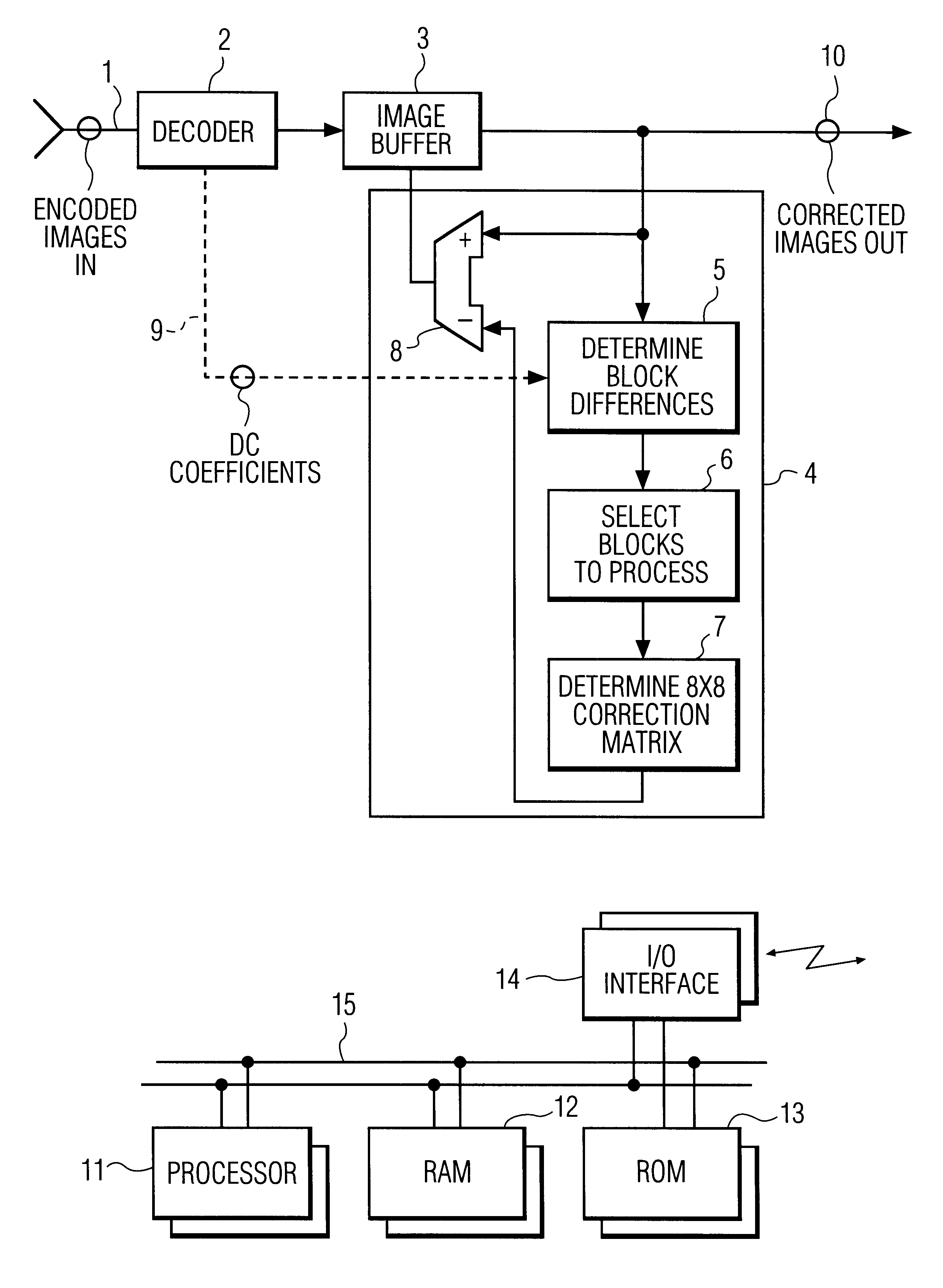
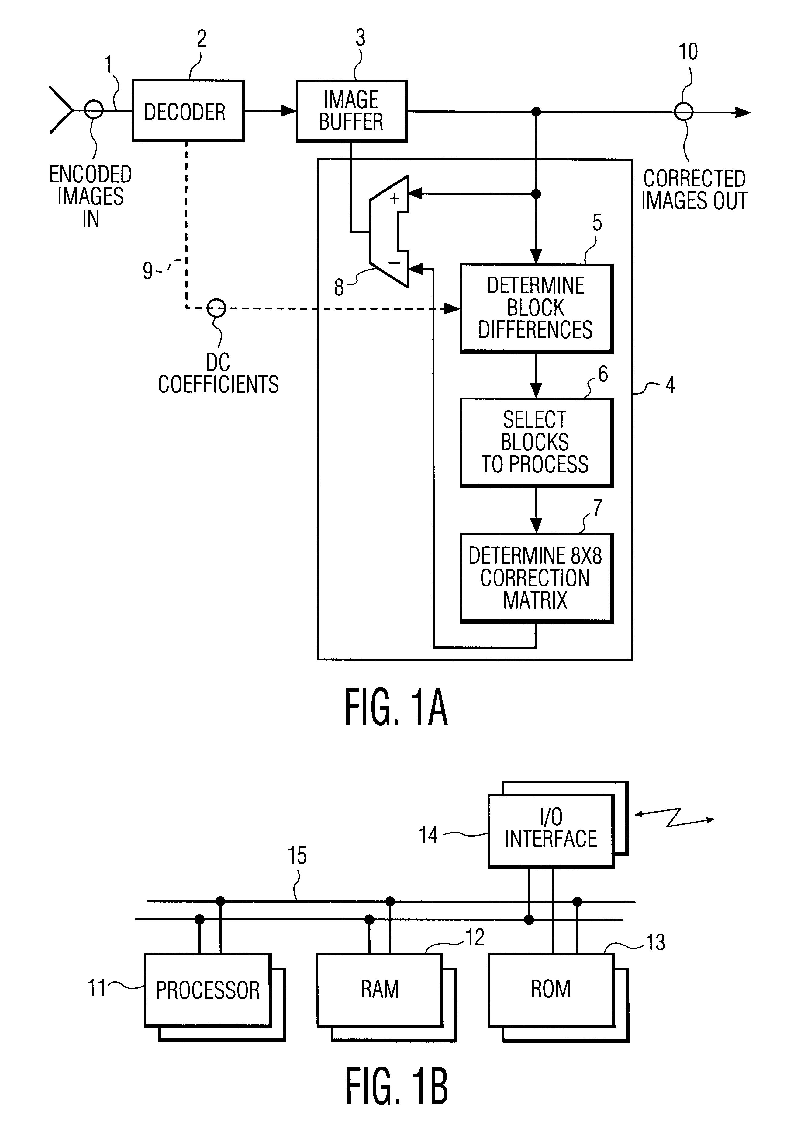
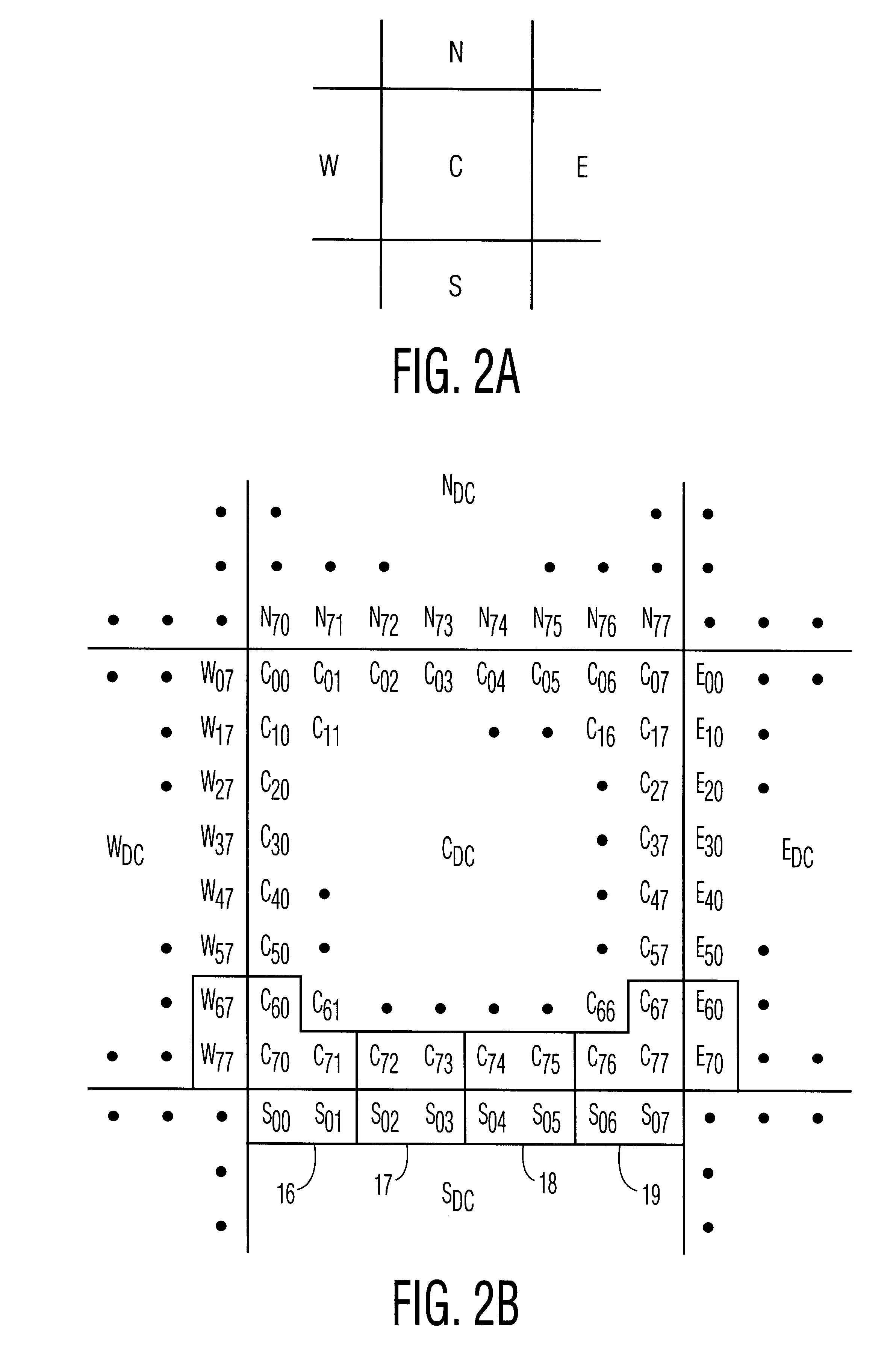
This invention relates to a system and method for reducing blocking artifacts introduced by current compression algorithms that compress images as independent blocks of pixels. Preferably, the methods of the invention include determining block-to-block differences in edge pixels or in overall intensities between adjacent pixel blocks, selecting pixel blocks for post-processing that appear to be in relatively featureless regions of the image, interpolating the block-to-block edge differences into a error correction matrix, and then subtracting the error correction matrix from the original pixel block. These methods are preferably implemented in special software routines that execute on micro-processor based systems or on digital signal processor based systems optimized for image decoding.

Description

1. Field of the InventionThe present invention relates to systems and methods for post-processing decompressed images in order to minimize perceptual artifacts due to prior image compression, and in particular to such prior image compression methods that process images as independent blocks of pixels.2. Description of the Related ArtMany important image compression methods process images as independent blocks of pixels. For example, such families of compression standards as JPEG, MPEG, H.320, and so forth, specify a step involving discrete cosine transformation ("DCT") of independent, non-overlapping 8.times.8 blocks of pixels in the source image followed by quantization of the resulting transform coefficients. See, e.g., Jack, 1996, Video Demystified, HighText Interactive Inc., San Diego, Calif. The quantized transform coefficients are transmitted from a transmitter-encoder to a receiver-decoder. Such transformation and quantization together achieve compression by exploiting the si...

Claims


Application Information

Patent Timeline
IPC IPC(8): G06T9/00G06T5/30G06T5/20H04N1/41H04N7/26
CPCG06T9/00
Inventor RACKETT, ALBERT E.
Owner ARRIS ENTERPRISES LLC
Learn More