Oxygen generating device

a generation device and oxygen technology, applied in the direction of respirators, carburetating air, separation processes, etc., can solve the problems of large volume, cumbersome use, difficult transportation,

Inactive Publication Date: 2001-11-20
ADVENT AEROBE
View PDF12 Cites 34 Cited by
  • Summary
  • Abstract
  • Description
  • Claims
  • Application Information

AI Technical Summary

Problems solved by technology

Oxygen generation devices are known in the art, however, they are either large, cumbersome, and difficult to use, necessitating that they be used in a medical office or hospital.

Method used


Image

  • Oxygen generating device
  • Oxygen generating device
  • Oxygen generating device

Examples


Embodiment Construction

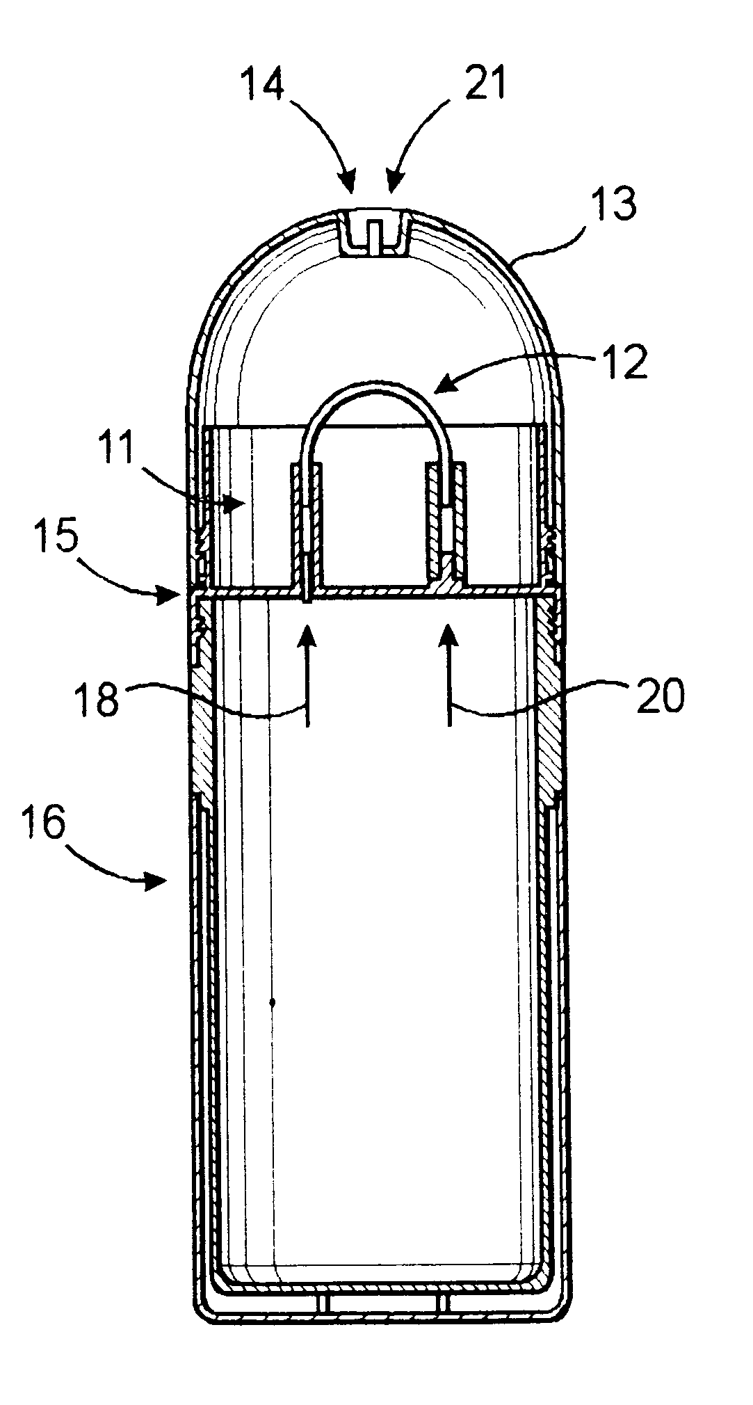
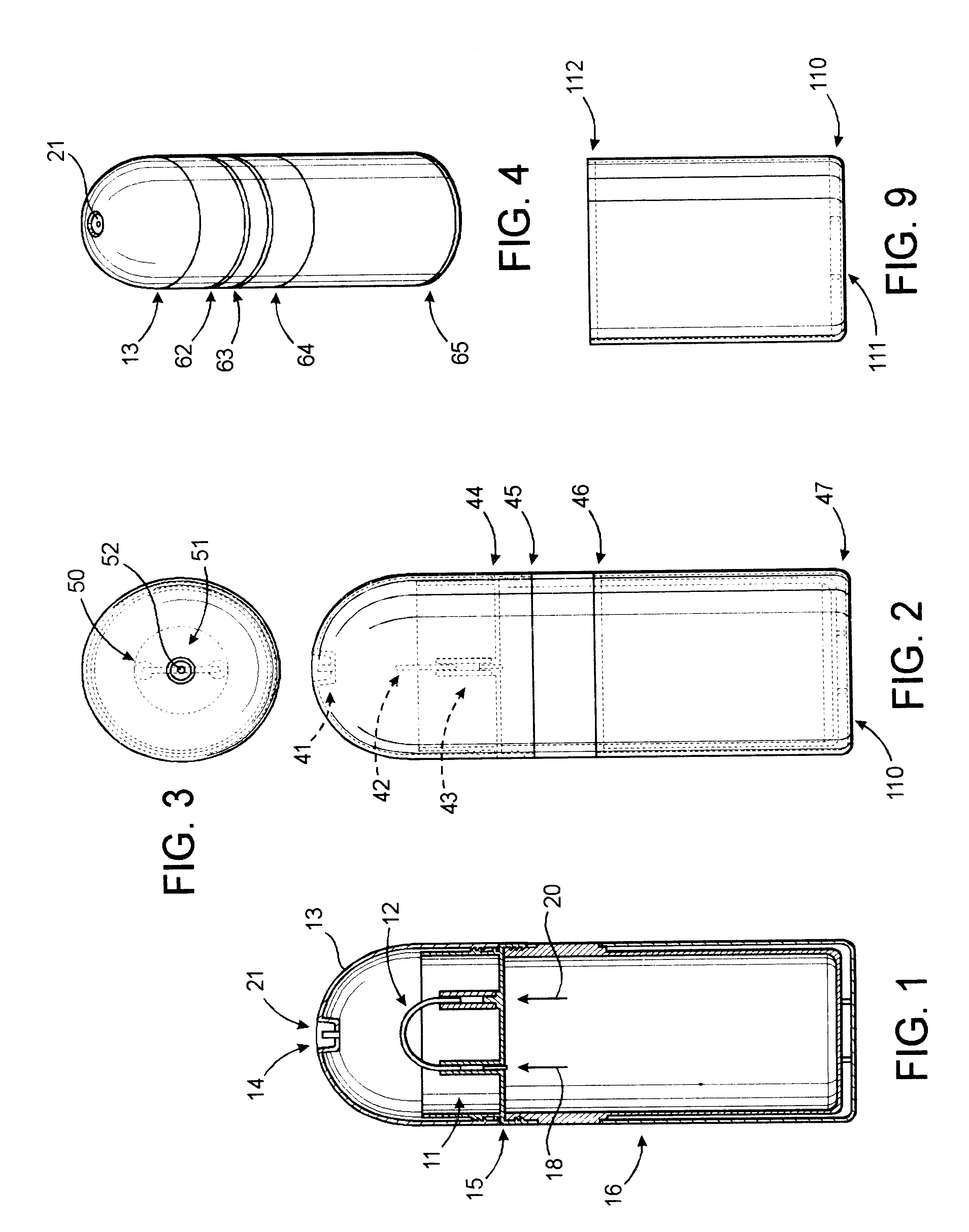
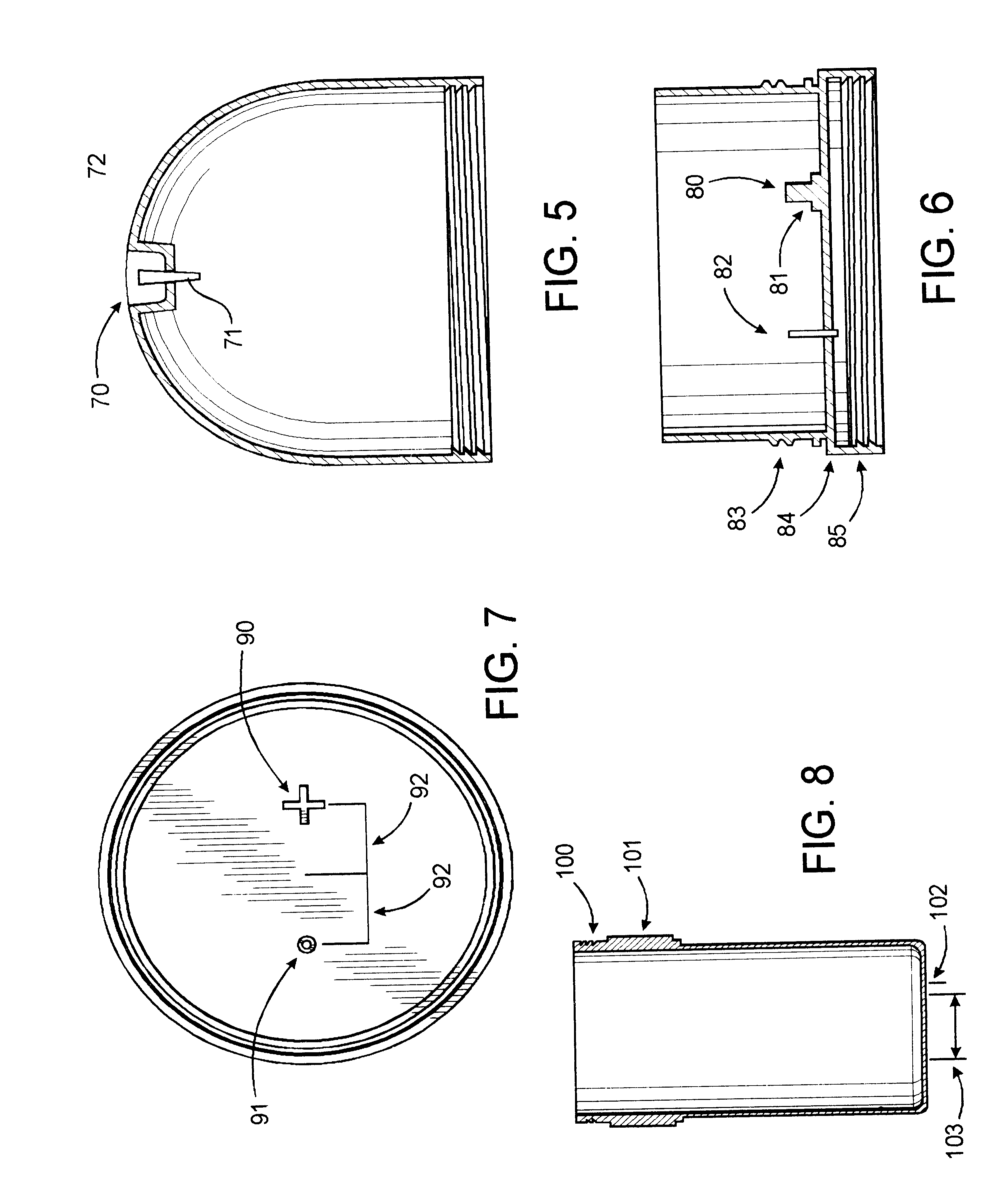
Referring to FIG. 1, reference number 18 depicts an oxygen generating device which has an upper portion, dome assembly 13, and a lower portion, tank assembly 23, wherein tank assembly 23 comprises a cylinder having a neck 15, to which the dome assembly, dome, and dome base 13 is attachable.

Number 14 is the edge of the nipple fitting 21 located at the top of dome assembly 13. The nipple fitting advantageously is a recessed assembly. Item 11 is the water level inside dome assembly 13. Lower portion 23 contains a tank 17 where the reaction occurs to produce oxygen. In addition to the oxygen producing chemical(s), water is advantageously added to tank 17. Item 19 is the inlet for oxygen developed in tank 17. Oxygen is forced by pressure developed by its generation in tank 17 into inlet 19. Tubing 12 receives oxygen from tank 17 through fittings at inlet 19, and delivers oxygen through bubble fitting 20 into water present in the lower portion of dome assembly 13. Optionally a bubble rest...


PUM

PropertyMeasurementUnit
Volumeaaaaaaaaaa
Foamaaaaaaaaaa
Heightaaaaaaaaaa

Abstract

The present invention is a oxygen generating device which comprises:a container having a mouth and a neck surrounding the mouth; a tank which has an annual flange for establishing a gas tight seal between the tank and the neck;a dome assembly which is engageable with the neck and extends upwardly to define a dome chamber above the neck; andmeans for permitting oxygen generated in the tank to flow into the dome chamber by bubbling through a liquid contained in the dome base;the dome base having an outlet connection through which oxygen can leave the chamber and where at least part of the dome is transparent so as to render the inside thereof visible from the outside of the dome.

Description

1. Field of the InventionThis invention relates generally to oxygen generation devices and more particularly to a chemical-generation, portable device usable by a patient or individual at home or in an emergency situation.2. Description of the Prior ArtOxygen generation devices are known in the art, however, they are either large, cumbersome, and difficult to use, necessitating that they be used in a medical office or hospital. Alternatively means of a size that can be used by a patient, such as high pressure oxygen cylinders are expensive, difficult to transport, and present an explosive or fire hazard.The present invention is a oxygen generating device which comprises: a container having a mouth and a neck surrounding the mouth; a tank which has an annual flange for establishing a gas tight seal between the tank and the neck;a dome assembly which is engageable with the neck and extends upwardly to define a chamber above the neck (dome chamber); andmeans for permitting oxygen gener...

Claims


Application Information

Patent Timeline
IPC IPC(8): B01J7/00A62B21/00C01B13/02A61M16/10A61M16/16
CPCA62B21/00B01J7/00C01B13/02A61M16/10A61M16/16
Inventor DU TOIT, WILLIAM
Owner ADVENT AEROBE
Why Eureka
Try Eureka