Controlling apparatus for elevator with divided control panel

a technology of control panel and control apparatus, which is applied in the direction of control system, ac motor control, elevator, etc., can solve the problems of increasing inertia efficiency, increasing cost, and increasing current electromagnetic nois

Inactive Publication Date: 2001-11-27
MITSUBISHI ELECTRIC CORP
View PDF17 Cites 36 Cited by
  • Summary
  • Abstract
  • Description
  • Claims
  • Application Information

AI Technical Summary

Problems solved by technology

In particular, in the case where the car travel is long or in the case where the car 2 has a large capacity and the drive power flowing through the cables becomes large, the following problem becomes remarkable.
Namely, since the drive power cable requires substantially the same length as the car travel because the car 2 rises and descends, and at the same time, durability against repeated bending is required, the cost therefor is increased.
Also, in the case where the traction motor 5 is inverter-driven, since a large current having a high frequency is caused to flow through the power cable, there is a fear that the current causes electromagnetic noise.
Also, in addition to the increased mass, in accordance with the increase of the number of the cables, there is a problem in that the inertia efficiency is increased upon the drive of the car and power that is needed for acceleration / deceleration is also increased.
According to this technique, the cable for the main circuit may be dispensed with, and also, the increase of the weight of the car may be restricted.

Method used


Image

  • Controlling apparatus for elevator with divided control panel
  • Controlling apparatus for elevator with divided control panel
  • Controlling apparatus for elevator with divided control panel

Examples


embodiment 1

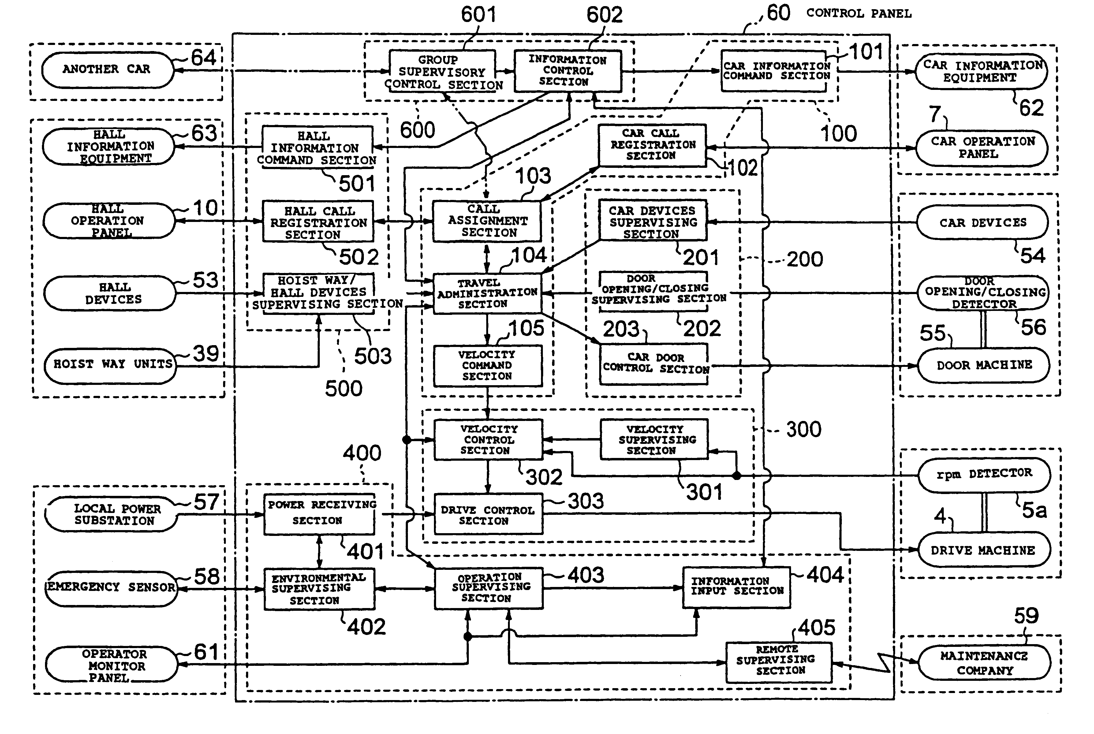
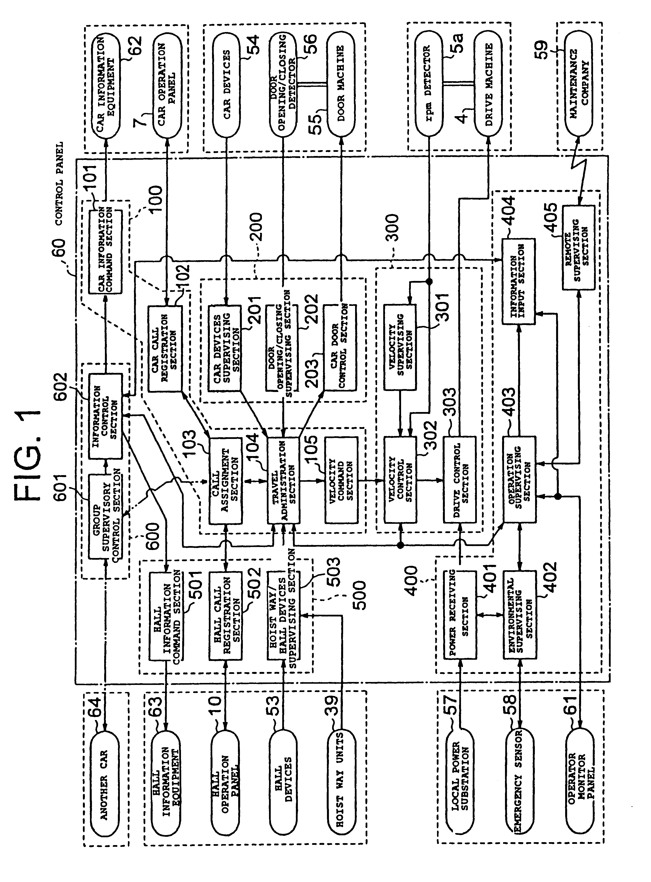
FIG. 1 is an overall structural view showing a connection relationship with peripheral devices while dividing a control panel of an elevator in accordance with every control function in embodiment 1 of this invention. FIG. 1 shows the connection of peripheral devices (surrounded by round rectangular solid lines) of the control panel while further dividing control panel functions of the elevator (the region surrounded by one-dot-and-dash lines in the drawing) in accordance with every function (surrounded by a rectangular solid line).

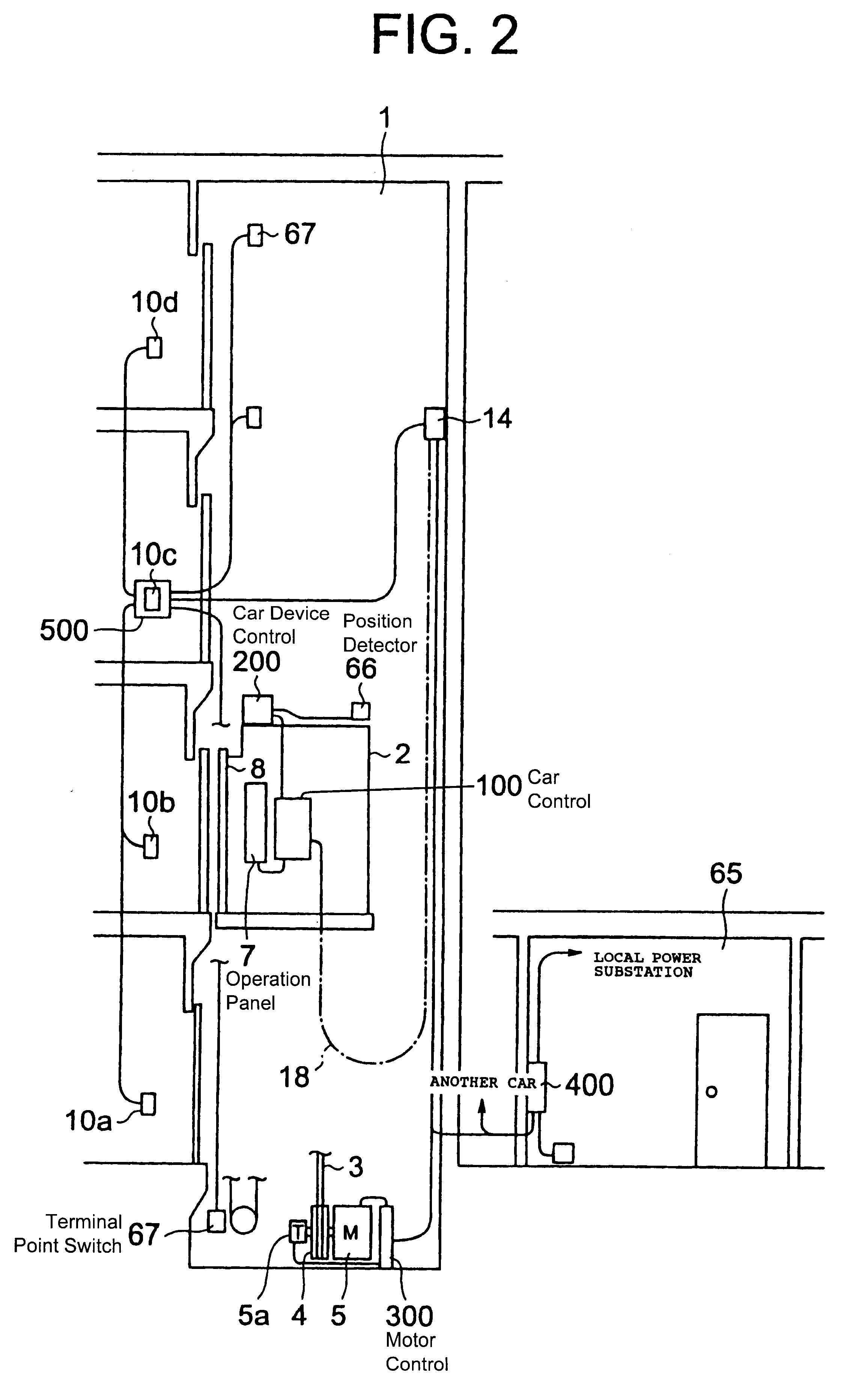
Also, FIG. 2 is a unit connection arrangement view concretely showing the connection arrangement of the structure shown in FIG. 1. Furthermore, FIG. 3 is a structural view showing a signal transmission system for mutually connecting the structure shown in FIG. 2.

As shown in FIG. 1, the control panel 60 in accordance with this invention is disposed at a position where it may be accessed from the inside of a car 2 (see FIG. 2). In particular, the control pa...

embodiment 2

FIG. 4 is an overall structural view showing an elevator where no machine room is provided in accordance with embodiment 2 of this i invention, and is a view of a traction type in which a drive machine 4 is disposed in an upper portion of a hoist way 1.

In FIG. 4, the same reference numerals are added to indicate the same structure as that of FIG. 10 and FIGS. 1 to 3. Numeral 4 denotes a drive machine for elevating and descending a car 2 installed in the upper portion of the hoist way 1, numeral 13 denotes a traction motor drive unit (also serving as a power source receiving function) installed immediately in the vicinity of the drive machine 4, and numeral 14 denotes a junction box installed in the hoist way 1 for relaying a cable between the car 2 and the hoist way installation unit. Also, numeral 15 denotes a cable for connecting the traction motor drive unit 13 and the traction motor 5, numeral 16 denotes a cable for connecting the traction motor drive unit 13 and the junction bo...

embodiment 3

FIG. 7 is a circuit diagram showing a controlling apparatus for an elevator in which a main power source may be turned on and off from the hall, in accordance with embodiment 3 of the present invention.

In FIG. 7, new numeral 41 denotes an electrical remote operation unit mounted on the circuit breaker 31 for enabling the turn-on and -off of electricity, and numeral 42 denotes a remote operation switch of the circuit breaker built in the hall operation panel 10 on a predetermined floor. The other structures are the same as those shown in FIG. 5, and the explanation therefor will be omitted.

In the structure shown in FIG. 7, the break or connection of the elevator power source is possible from the hall to thereby further enhance the maintenance property. Also, although not shown, if a small-sized switch is used for the remote operation switch 42 provided within the hall operation panel 10, even if the hall operation panel 10 is small in size, it is possible to assemble it into the pane...


PUM


Abstract

A control panel is divided into units in accordance with each control function, units to be controlled by or connected to the divided unit are divided into unit groups in accordance with a place where the unit is to be disposed, and unit groups having a relationship form a control section, the control section being disposed in the vicinity of the unit group so that it is unnecessary to provide a large integral control panel. There is no difficulty in finding an installation place for the control panel, it is unnecessary to prepare a special machine room, it is possible to provide the control panel in an empty space around the respective unit to be controlled, and to effectively use the building while enhancing the layout of the units and it is possible to quickly control a localized situation for the unit to be controlled.

Description

The present invention relates to a controlling apparatus for an elevator, and more particularly to an arrangement of a control board.TECHNICAL BACKGROUNDFIG. 10 is a block diagram showing an overall structure of a controlling apparatus for an elevator, which does not require an elevator machine room, as shown in Japanese Patent Application Laid-Open No. Hei. 9-267978. Namely, a control board which has been installed in a conventional machine room is mounted on a car and in one piece with a door drive device that is mounted on the car.In FIG. 10, numeral 1 denotes a hoist way, numeral 2 denotes a car, numeral 3 denotes a main rope, numeral 4 denotes a drive machine disposed within the hoist way for elevating / descending the car 2 through the rope 3, numeral 5 denotes a traction motor for driving the drive machine 4, numeral 6 denotes a control panel mounted within a car for performing an operational control of the car 2, a drive control of the traction motor 5 or the like, numeral 7 d...

Claims


Application Information

Patent Timeline
Patent Type & Authority Patents(United States)
IPC IPC(8): B66B1/34B66B11/00
CPCB66B1/34B66B1/3415B66B1/3446B66B11/001
Inventor YAMAKAWA, SHIGEKI
Owner MITSUBISHI ELECTRIC CORP
Why Eureka
Try Eureka