Encased overhead door operator having threadably attached mounts

a technology of overhead doors and mounts, which is applied in the direction of door/window fittings, construction fastening devices, and construction, etc., can solve the problems of contaminating the screw mechanism and/or the linear bearing, and limiting the available span between supports

Inactive Publication Date: 2001-12-04
WESTINGHOUSE AIR BRAKE CO
View PDF21 Cites 27 Cited by
  • Summary
  • Abstract
  • Description
  • Claims
  • Application Information

AI Technical Summary

Benefits of technology

Yet another object of the present invention is to provide a motorized door drive for a door that covers and uncovers a door opening which requires a minimal number of attachments to structures adjacent the door opening.
A further object of the present invention is to provide a motorized door drive for a door that covers and uncovers a door opening which requires a minimum number of fasteners to attach it to structures adjacent the door opening.
It is an additional object of the present invention to provide a motorized door drive for a transit vehicle door which requires attachment only at its ends so that load induced camber of the vehicle does not affect the door drive.

Problems solved by technology

This linkage presents design problems because it must transmit a drive force to the door panel and it must accommodate misalignment between the two systems.
Systems presently on the market are also open to dust, dirt, metal chips etc, causing contamination of the screw mechanism and / or of the linear bearings.
This limits the available span between supports.

Method used


Image

  • Encased overhead door operator having threadably attached mounts
  • Encased overhead door operator having threadably attached mounts
  • Encased overhead door operator having threadably attached mounts

Examples


Embodiment Construction

, particularly, when the detailed description is taken in conjunction with the attached drawing figures and with the appended claims.

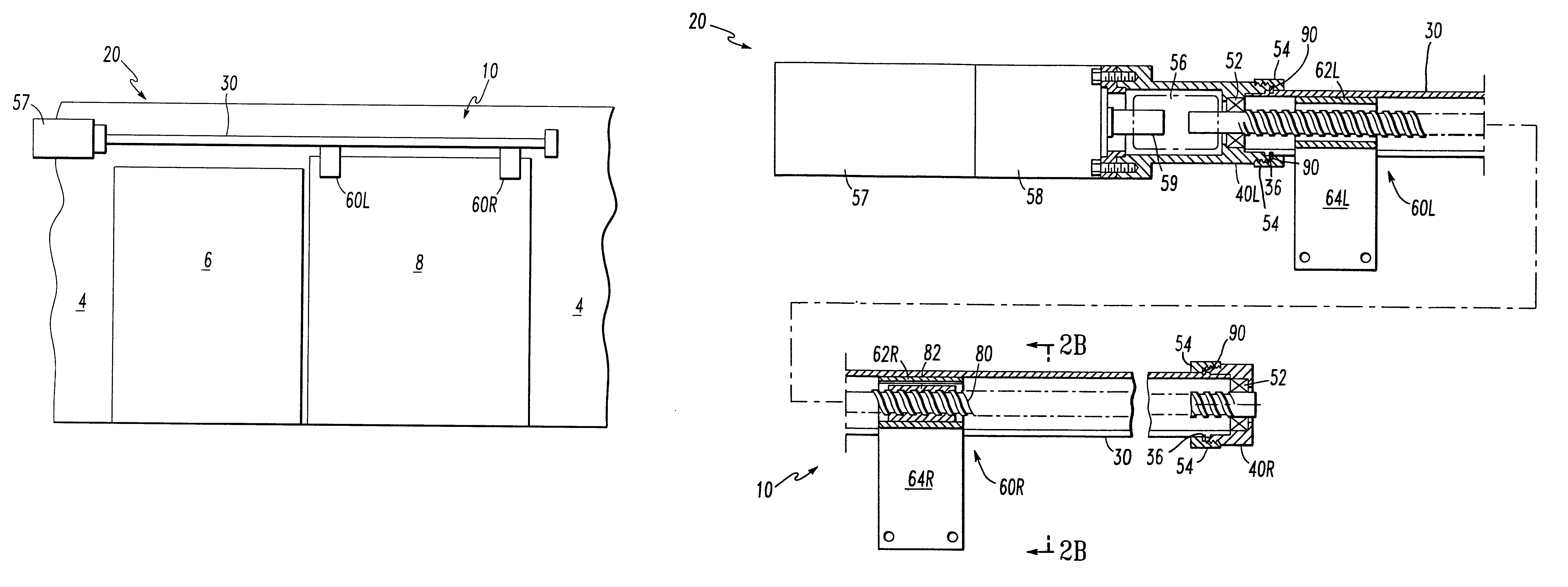
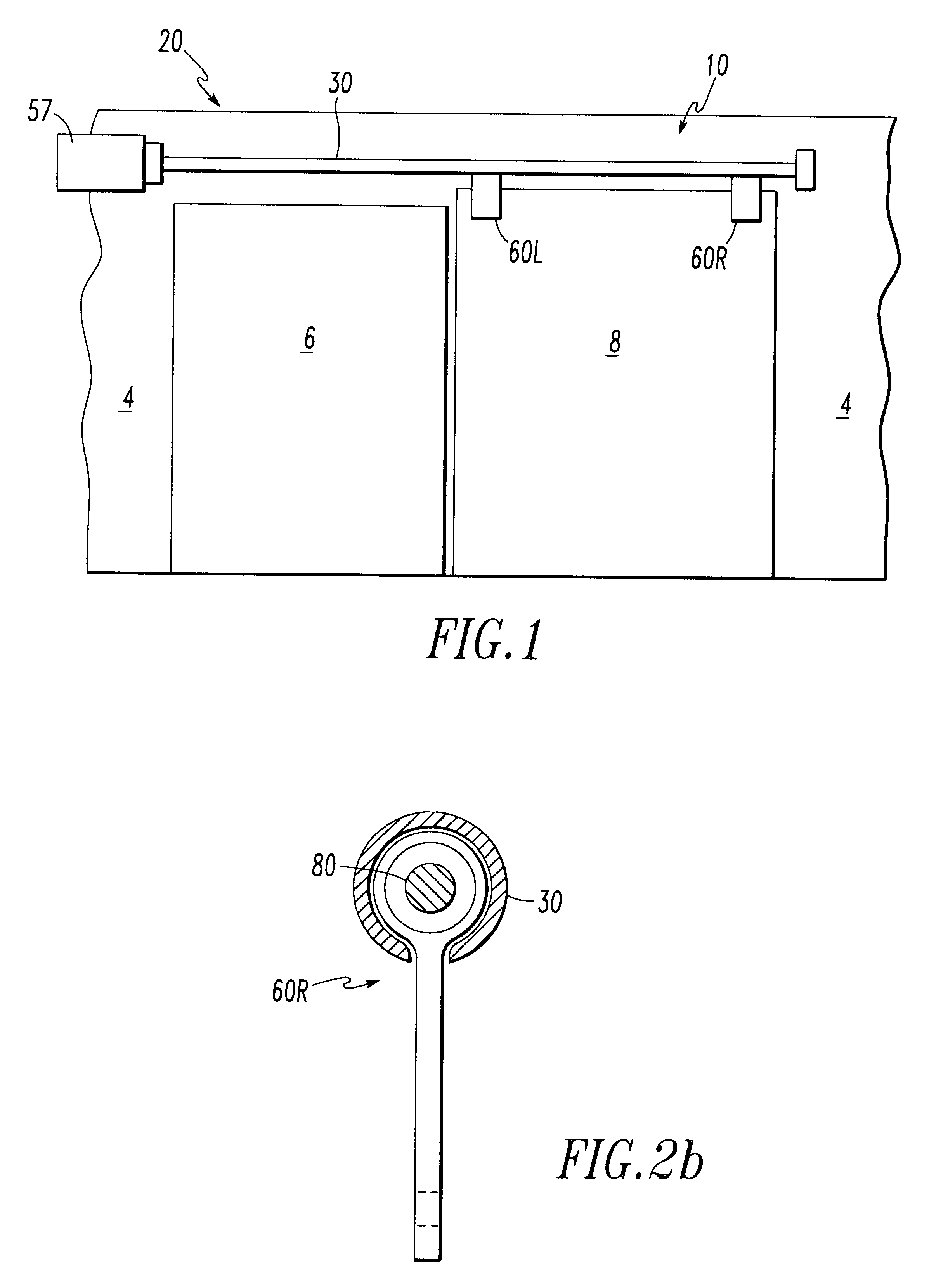
FIG. 1 is a side elevation view of the invention used to open and close a sliding door.

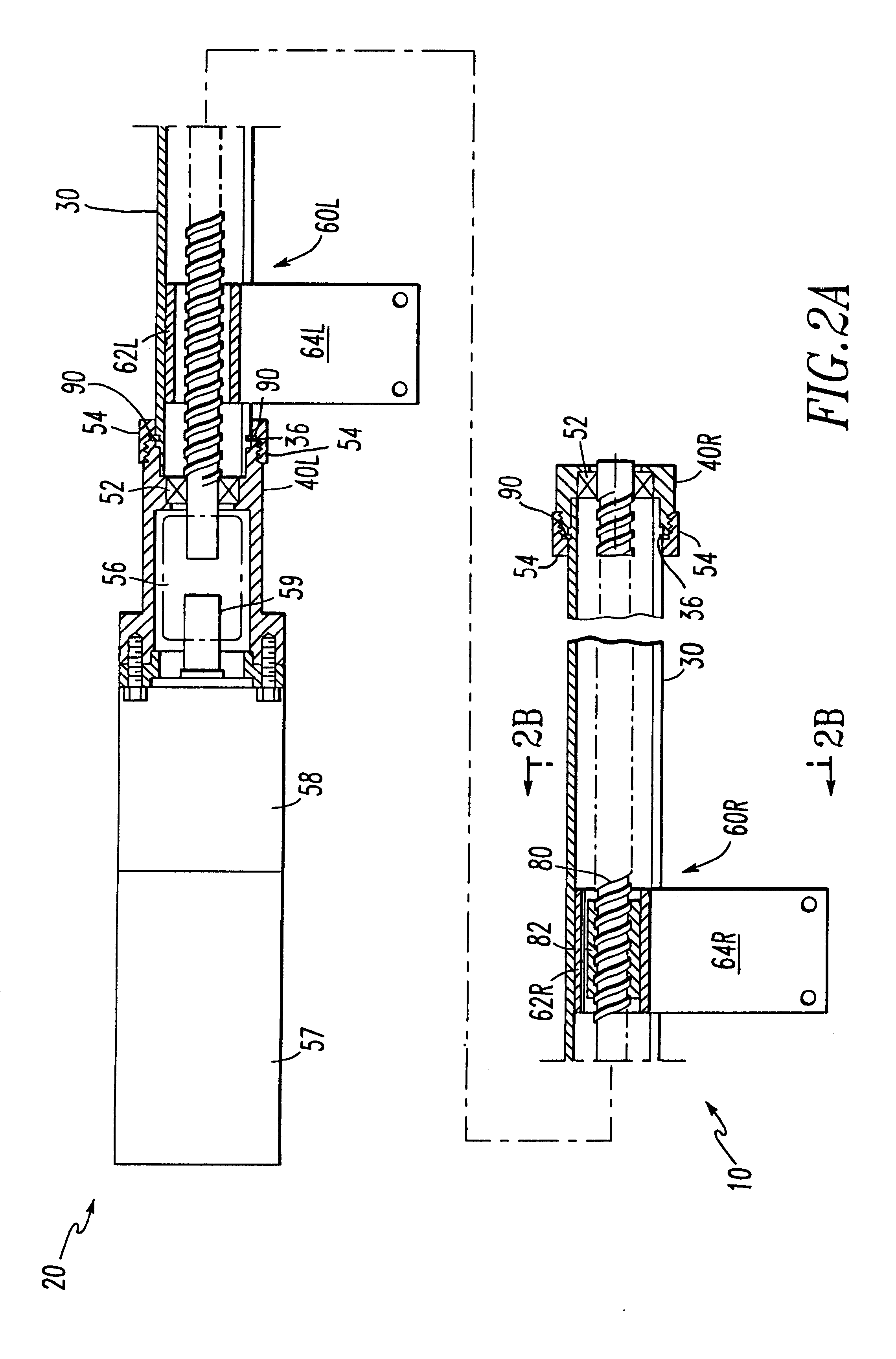
FIG. 2A is a side view, partially in cross section of the presently preferred embodiment of the invention.

FIG. 2B is a cross-sectional view of the invention taken along the line 2B--2B in FIG. 2A.

FIG. 3A is a side view of the slotted tube of the invention.

FIG. 3B is an end view of the slotted tube shown in FIG. 3A.

FIG. 4A is a side view, partially in cross section, of the drive hanger.

FIG. 4B is an end view of the drive hanger.

FIG. 4C is a detail view of a longitudinal anti-rotation groove in the drive hanger.

FIG. 4D is a detail view of a circumferential groove for a retaining ring in the drive hanger.

FIG. 5A is a side view of a hanger having lubrication grooves.

FIG. 5B is an end view of the hanger which has lubrication grooves.

FIG. 5C is a cross-sectional view of th...


PUM


Abstract

A door support and drive mechanism for a door can be mounted either over or in a door opening in a transit vehicle or other structure. The mechanism includes a tube which has a longitudinal slot. The mechanism also has mounts attached to the tube for mounting the mechanism to the structure over the door opening, so that the tube is substantially horizontal and the slot is along a lower portion of the tube. The mechanism includes at least one door hanger which has an upper portion movably disposed within the tube and a depending portion passing through the slot, the depending portion being for attachment to the door. The mechanism has a drive nut attached to the door hanger. A drive screw is positioned in the tube, engaging a threaded inner portion of the drive nut. The drive screw is connectable to a rotary power device to be rotated thereby. Rotation of the drive screw causes longitudinal movement of the drive nut and the hanger to which the drive nut is attached, so that the door is moved longitudinally.

Description

The present invention relates, in general, to motorized sliding doors and, more particularly, the instant invention relates to a suspension and drive mechanism for transit vehicle doors.Overhead sliding door operators presently on the market consist of two basic systems.(1) They have a load bearing system which supports the weight of the door panel or panels and allows movement of the door. This is normally accomplished by using a precision shaft and linear bearings, or rollers, supported in a C-shaped, bent or extruded, member. Doors are generally supported by door hangers which are free to move along horizontal rods or tracks.(2) Door operators also have mechanisms for moving the doors. A belt and pulley system, for example, may be used to move the doors. Alternatively, overhead door operators may employ a helical drive member which engages a drive nut attached to a door hanger. A motor is used to rotate the helical drive and this causes movement of the nut along the drive.These t...

Claims


Application Information

Patent Timeline
Patent Type & Authority Patents(United States)
IPC IPC(8): E05F15/14
CPCE05F15/652E05Y2900/51E05Y2201/434E05Y2201/696E05Y2201/70
Inventor STEPHEN, ERICH P.
Owner WESTINGHOUSE AIR BRAKE CO
Why Eureka
Try Eureka