Coupling device for a point actuator and/or lock

a technology of coupling device and point actuator, which is applied in the direction of transportation and packaging, railway signalling, roads, etc., can solve the problem of unfavorable non-release of the switch

Inactive Publication Date: 2001-12-04
VAE AG
View PDF8 Cites 7 Cited by
  • Summary
  • Abstract
  • Description
  • Claims
  • Application Information

AI Technical Summary

Problems solved by technology

If, in addition, articulations tolerate an additional play,

Method used


Image

  • Coupling device for a point actuator and/or lock
  • Coupling device for a point actuator and/or lock
  • Coupling device for a point actuator and/or lock

Examples


Embodiment Construction

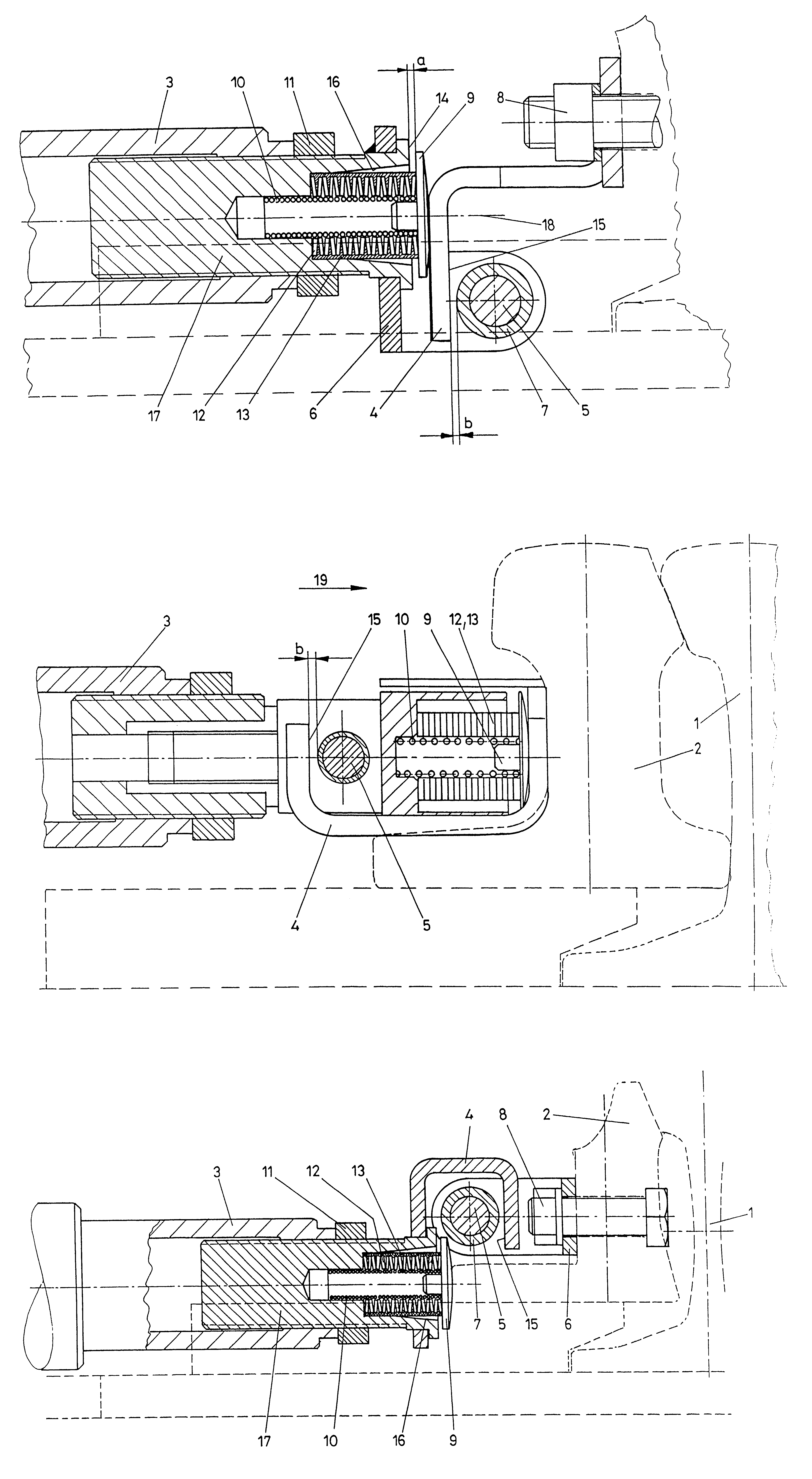
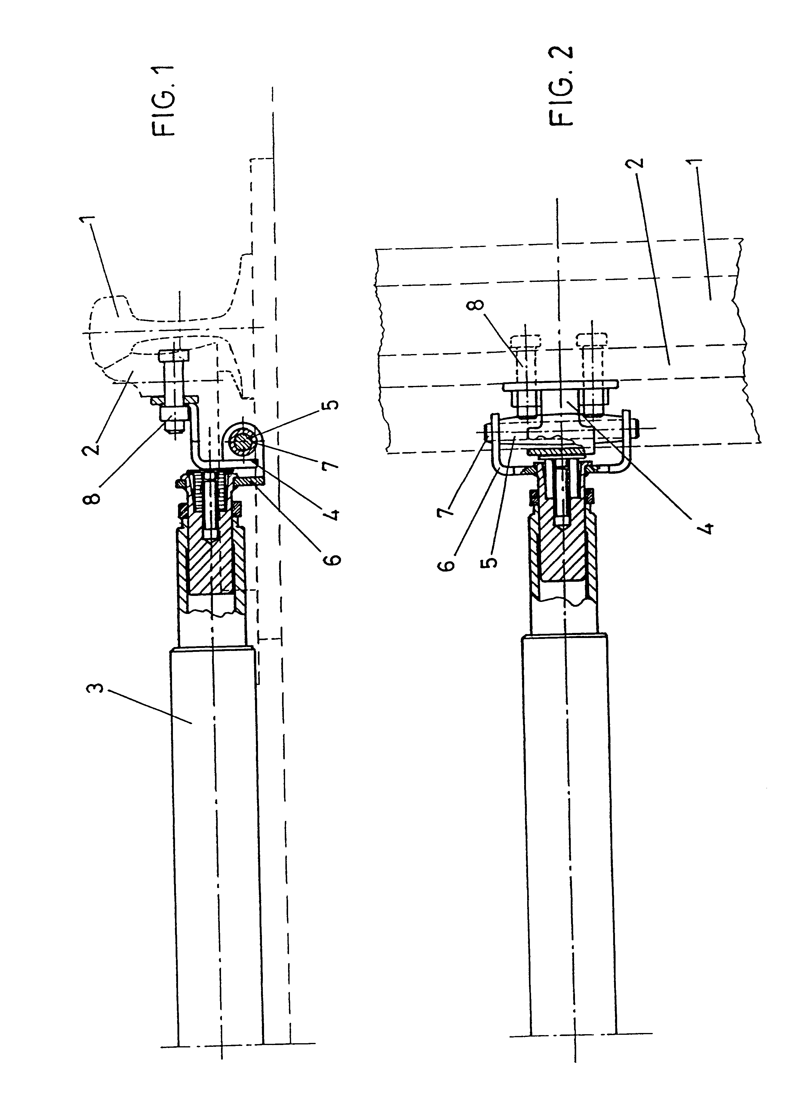
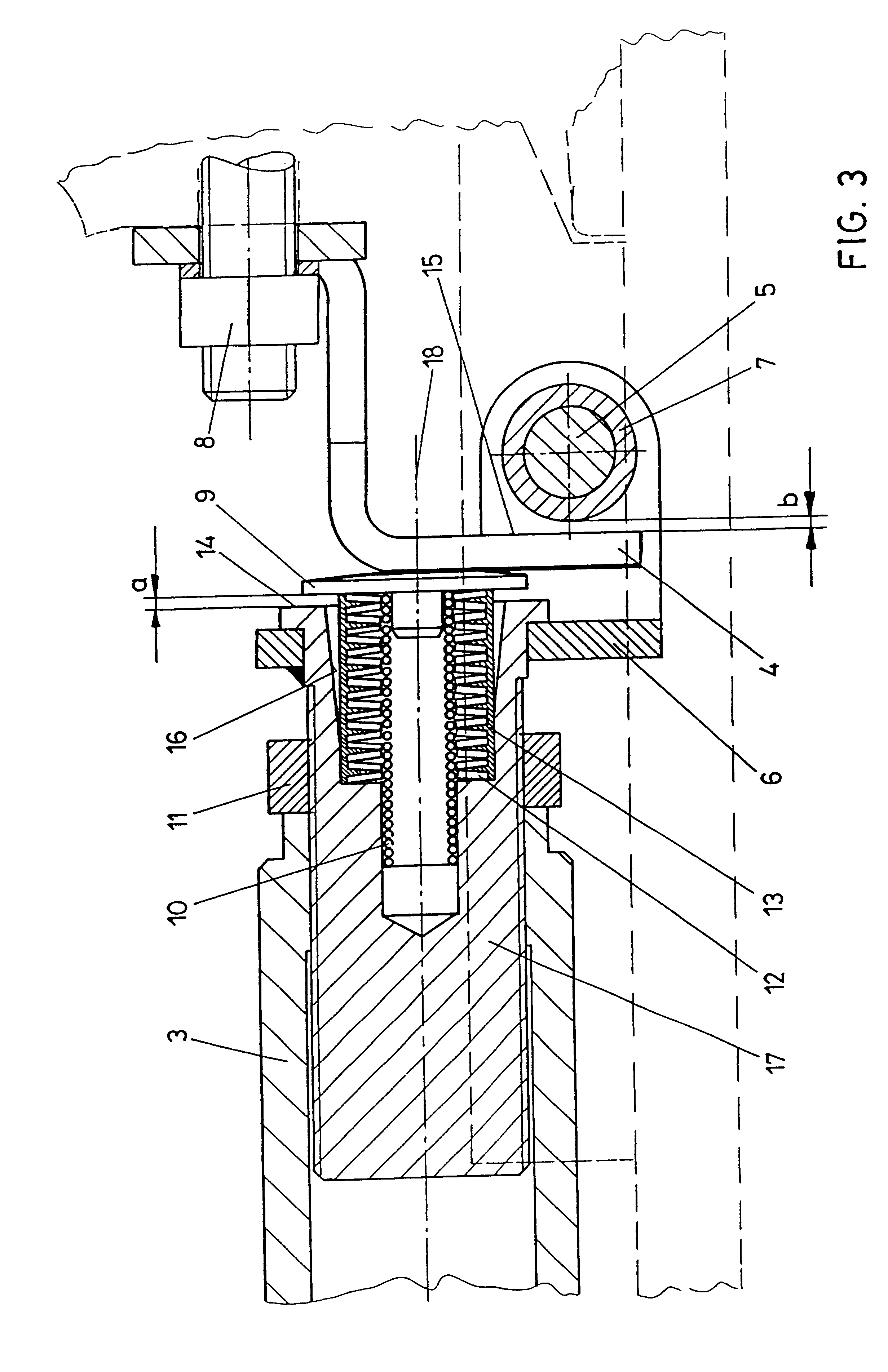
In FIG. 1, 1 denotes a standard rail toward which a switch tongue 2 may be pressed. The switch actuator 3 comprises an integrated lock and enables the switch tongue 2 to be pressed towards the standard rail 1 or to be moved away from the standard rail. The transmission of the tensile forces required for moving the switch tongue 2 away from the standard rail 1 is effected via a cranked strap 4 which cooperates with a pin 5. The pin 5 is fixed in a fork-shaped lug 6 and carries a cambered jacket tube 7 such that only a line contact exists between the strap 4 and the jacket tube 7 as tensile forces are being transmitted.

The strap 4 is rigidly connected with the switch tongue 2 via screw bolts 8.

In the top view according to FIG. 2, the cambered outer contour of the pin 5 is to be seen and the forked shape of the lug 6 carrying the pin is, furthermore, apparent. The lug 6 encompasses parts of the strap 4 such that a compact mode of construction is rendered feasible.

The details of the con...


PUM


Abstract

In a connecting device for a switch actuator and/or a lock for movable parts of a railway switch or crossing, including a rod assembly, in particular a sliding rod or a locking rod articulately connected with the movable part, the movable part or the rod assembly, in particular the switch tongue (2), is rigidly connected with a strap (4) engaging from behind a pin (5) connected with the rod assembly or the movable part for transmitting tensile forces. Between the rod assembly and the strap (4) or the movable part is arranged at least one elastic compression element, which is compressible by the rod assembly in the abutment position of the movable part on a rigid rail part, the strap (4) being displaceable out of abutment on the pin (5).

Description

1. Field of the InventionThe invention relates to a connecting device for a switch actuator and / or a lock for movable parts of a railway switch or crossing, including a rod assembly, in particular a sliding rod or a locking rod articulately connected with the movable part.2. Prior ArtSwitch actuators of the initially defined kind are described, for instance, in AT-B 388 198 and EP-B1 603 156. In the configuration according to AT-B 388 198 a long-hole connection is provided, via which a locking clamp that is displaceable by means of a sliding rod is articulately connected with the switch tongue. In EP-B1 603 156, which introduced a switch actuator with an integrated lock or a locking device, respectively, the connection with the movable rail tongue is realized via a joint piece which is articulately connected with the lock, or with the foot of the switch tongue, via pins. In those configurations, both tension and pressure are transmitted via the pin connection, wherein an additional ...

Claims


Application Information

Patent Timeline
IPC IPC(8): B61L5/00B61L5/10
CPCB61L5/00B61L5/10
Inventor ACHLEITNER, HERBERTHORTLER, JOSEF
Owner VAE AG
Why Eureka
Try Eureka