Device for writing on thermographic material

Inactive Publication Date: 2001-12-04
AGFA GEVAERT HEALTHCARE
View PDF13 Cites 12 Cited by
  • Summary
  • Abstract
  • Description
  • Claims
  • Application Information

AI Technical Summary

Benefits of technology

to provide a compact device based on conventional devices, which mak

Problems solved by technology

The pre-heating step, however, is designed to not induce writing on the thermographic material.
Since the required optical path is quite long, it may not be possible to accurately steer the laser beam.
LED's emit light at very low energy and can therefore not be used to write on thermographic material.
Moreover, the requ

Method used


Image

  • Device for writing on thermographic material
  • Device for writing on thermographic material
  • Device for writing on thermographic material

Examples


first embodiment

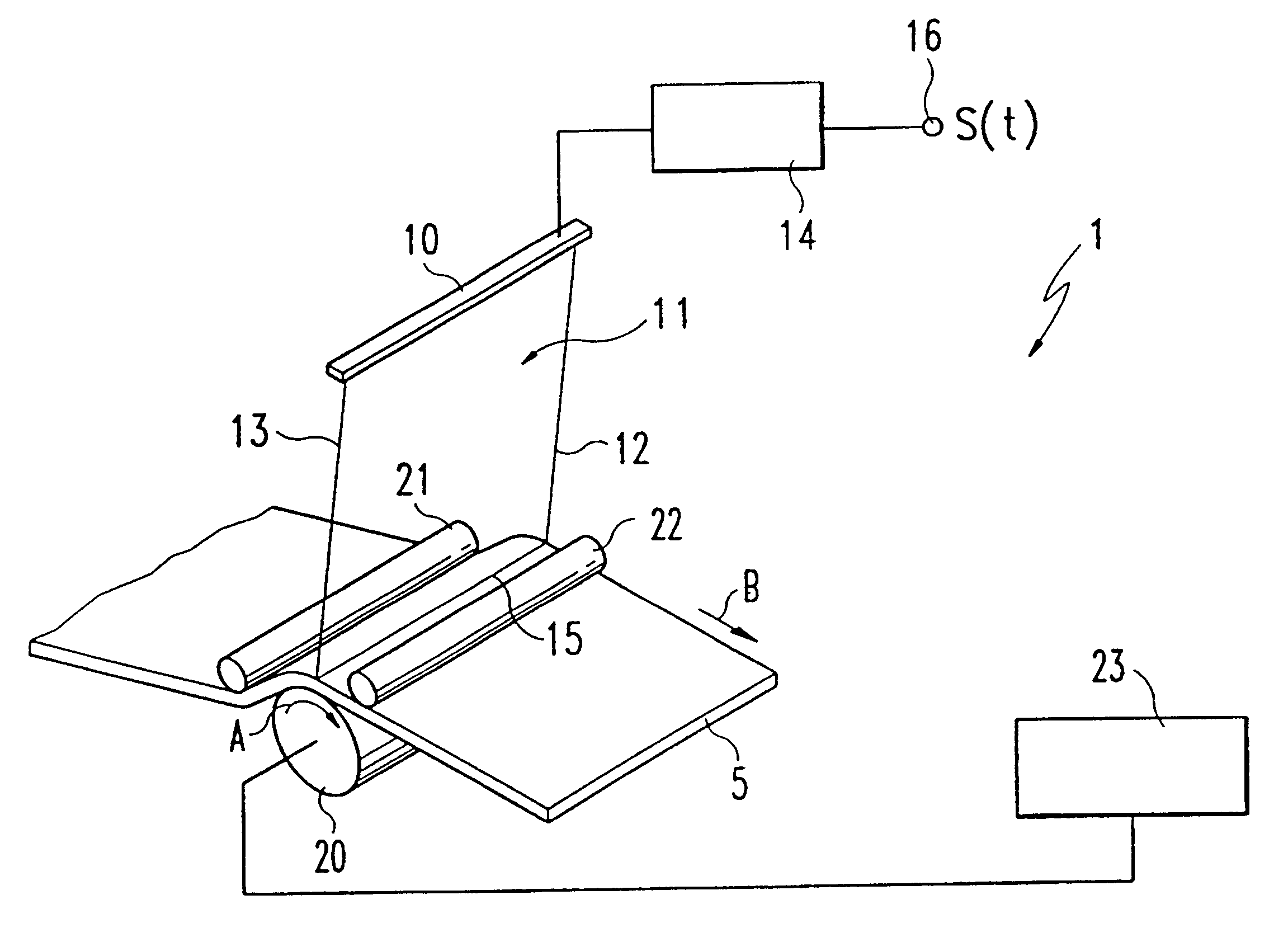
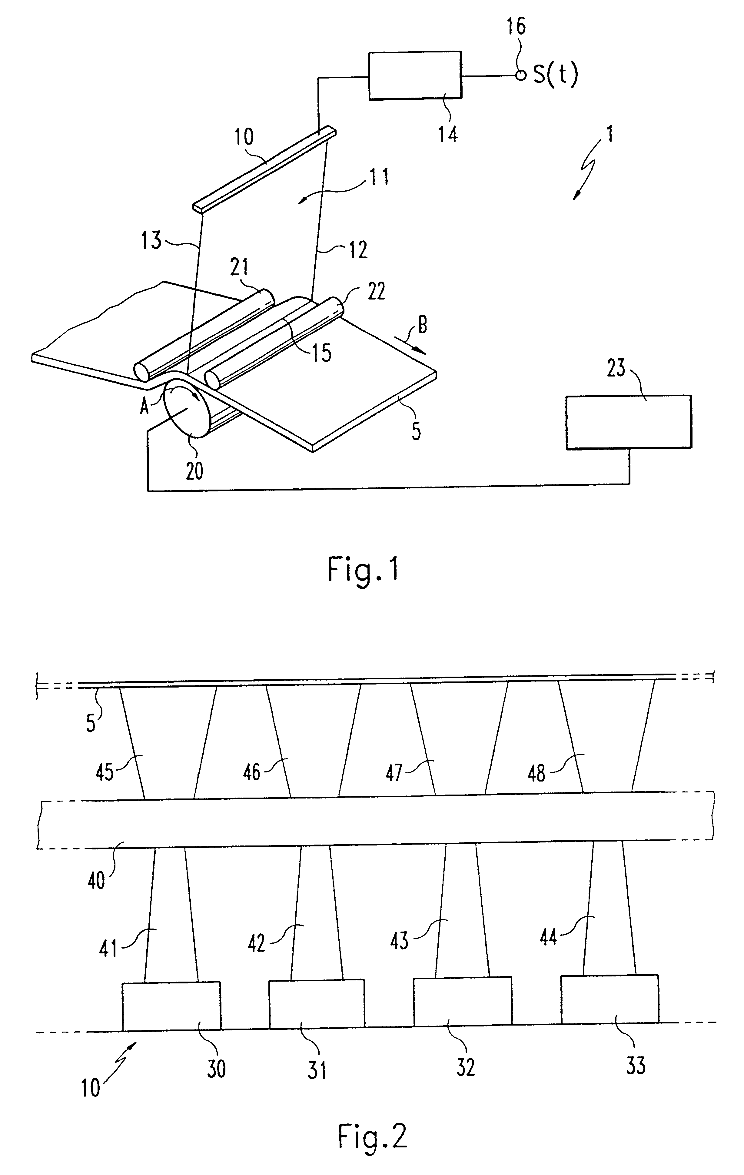
FIG. 1 shows the writing device 1 according to the invention for writing on thermographic material 5. The writing device 1 includes a laser row 10 which represents a writing instrument for writing on the thermographic material 5 using a specified information signal s(t). The information signal s(t) is applied to an input interface 16 of a laser row controller 14 and includes information about an image to be recorded on the thermographic material 5. The information signal s(t) applied to the input interface 16 can originate, for example, from a recording device for medical applications. The information signal s(t) used to address the laser row 10 is processed in the laser row controller 14. The laser row includes a plurality of individually addressable lasers which are directed towards the thermographic material 5. The laser row 10 can be used to write on a row 15 of the thermographic material 5 by blackening the thermographic material 5. The laser row 10 is spaced apart from the the...

second embodiment

FIG. 2 shows the device according to the invention depicting the beam path of the point sources in operation. In this example, the point sources are also lasers. FIG. 2 shows a section of the laser row 10 with four lasers 30-33 arranged side-by-side. The lasers 30 to 33 are shown in operation, when emitting a respective laser beam 41-44. The laser beams 41-44 in the present exemplary embodiment are directed perpendicular to the thermographic film 5 to be written. A lens 40 is disposed between the lasers 30-33 and the film 5. This lens 40 is a commercially available so-called SELFOC lens. The optical lens 40 is used to affect the radiation energies of the beam path 41-44 of the lasers 30 to 33 and to ensure that the laser beams of lasers 30-33 strike the thermographic film 5 exactly at the associated pixels. The beam path 41-44 of the lasers 30-33 is therefore converted by the optical lens 40 into the beam path 45-48 located between the lens 40 and the film 5. The lens should be able...

third embodiment

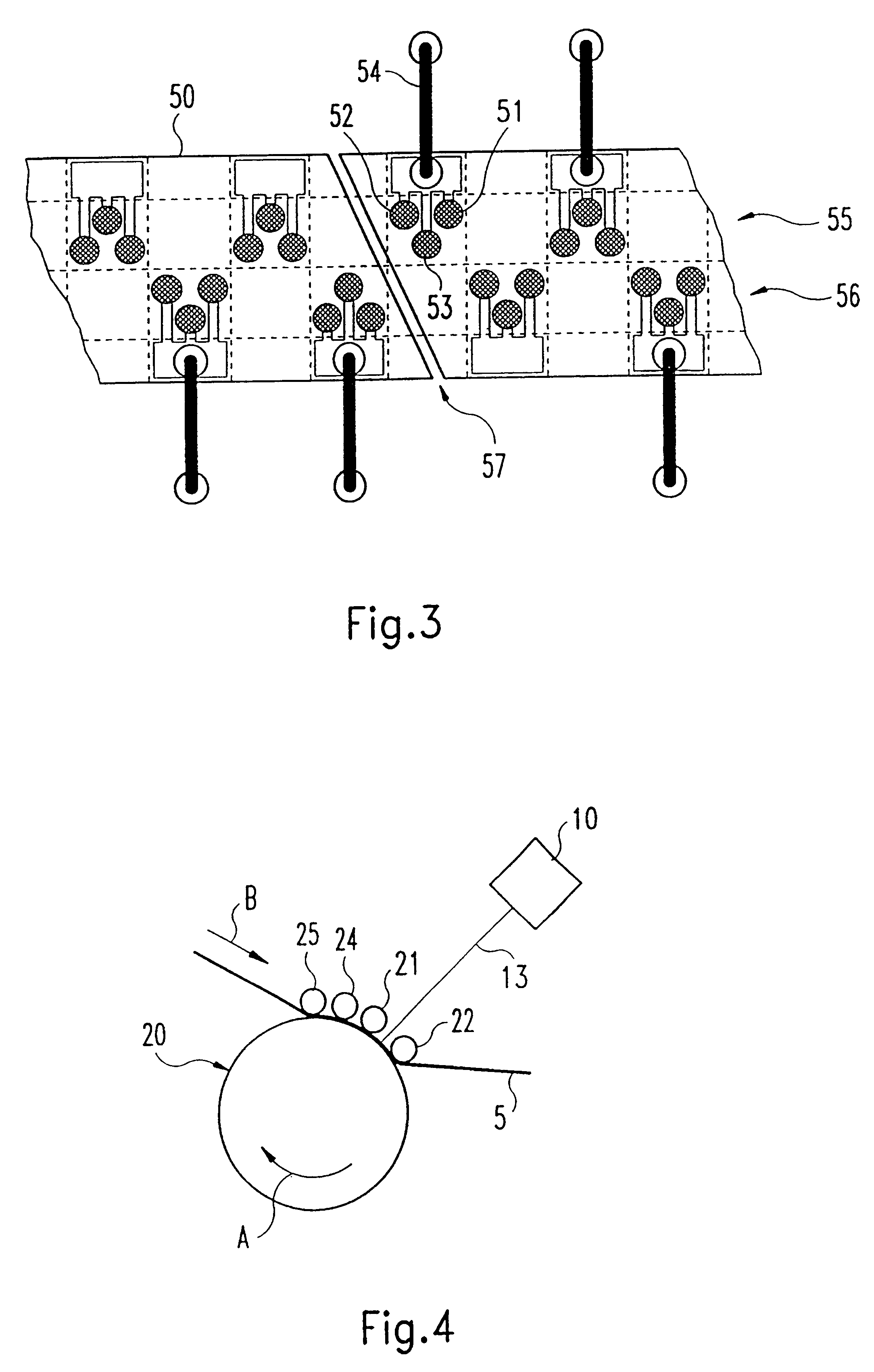
FIG. 4 shows the device according to the invention having several pressure rollers which press the thermographic film 5 against the heating drum 20. According to FIG. 4, a third pressure roller 24 and a fourth pressure roller 25 are placed before the first pressure roller 21. Pre-heating the film 5 with several pressure rollers 21, 24 and 25 increases the length of the contact path between the thermographic film 5 and a surface of the heating drum 20 and consequently also the time during which the heating drum 20 pre-heats the thermographic film 5. In this way, the pre-heating conditions for thermographic material 5 can be tailored to different thermographic material. The duration of the pre-heating step can be extended or shortened depending on the composition and the characteristic properties of the different thermographic materials. In addition, the thermographic material 5 can be pre-heated more accurately to a temperature below the writing temperature.


PUM


Abstract

The invention relates to a device (1) for writing on thermographic material (5). The inventive device (1) comprises a heater (20) with which the thermographic material (5) is preheated to a temperature, which is lower than a writing temperature. The thermographic material (5) can be written on with a writing instrument (10) which is distanced from the thermographic material (5) after input of an information signal (s(t)). The writing instrument (10) has a plurality of individually controllable point sources (30-33; 51-53). The thermographic material (5) can be written on in a point-by-point manner with said point sources (30-33; 51-53).

Description

1. Field of the InventionThe present invention relates to a device for writing on thermographic material. This device includes a heater for pre-heating the thermographic material to a temperature below a writing temperature required for writing on the thermographic material, and a writing instrument for writing on the thermographic material according to a predefined information signal s(t), wherein the writing instrument is spaced apart from the thermographic material.2. Description of the Related ArtA device of this type is described in EP 0 734 870 A2. This known device preheats a thermographic material using a heater in form of a rotatably supported heater drum to a temperature below a writing temperature of the thermographic material. The pre-heating step, however, is designed to not induce writing on the thermographic material. The light beam of a single laser is projected on the thermographic material using an optical device. The laser is modulated with an information signal. ...

Claims


Application Information

Patent Timeline
IPC IPC(8): B41J2/475B41J2/32B41J2/00B41J2/48
CPCB41J2/4753
Inventor BETZOLD, WOLFRAMOELBRANDT, LEOSTUMPF, FRIEDRICHZEHETMAIER, THOMASHOOGMARTENS, IVANLEENDERS, LUCSTRIJCKERS, HANSGEBELE, HERBERTKAPPELER, FRANZ
Owner AGFA GEVAERT HEALTHCARE
Why Eureka
Try Eureka