

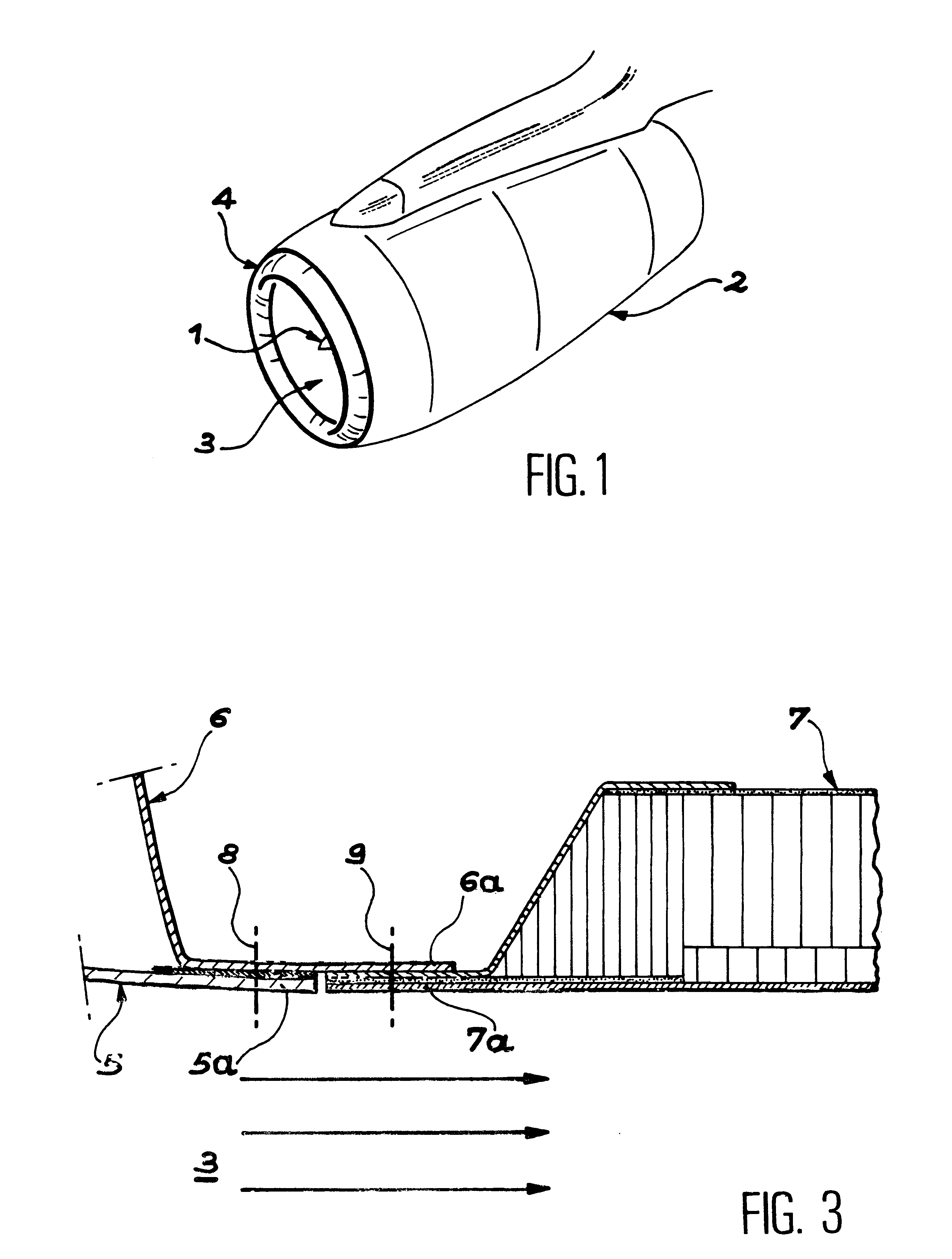
Air intake structure for aircraft engine
a technology for air intake and aircraft engine, which is applied in the direction of turbine/propulsion air intake, air transportation, vehicles, etc., can solve the problems of affecting maintenance personnel, dimensional references, and assembly losing all its rigidity,
- Summary
- Abstract
- Description
- Claims
- Application Information
AI Technical Summary
Problems solved by technology
Method used
Image

Examples
first embodiment
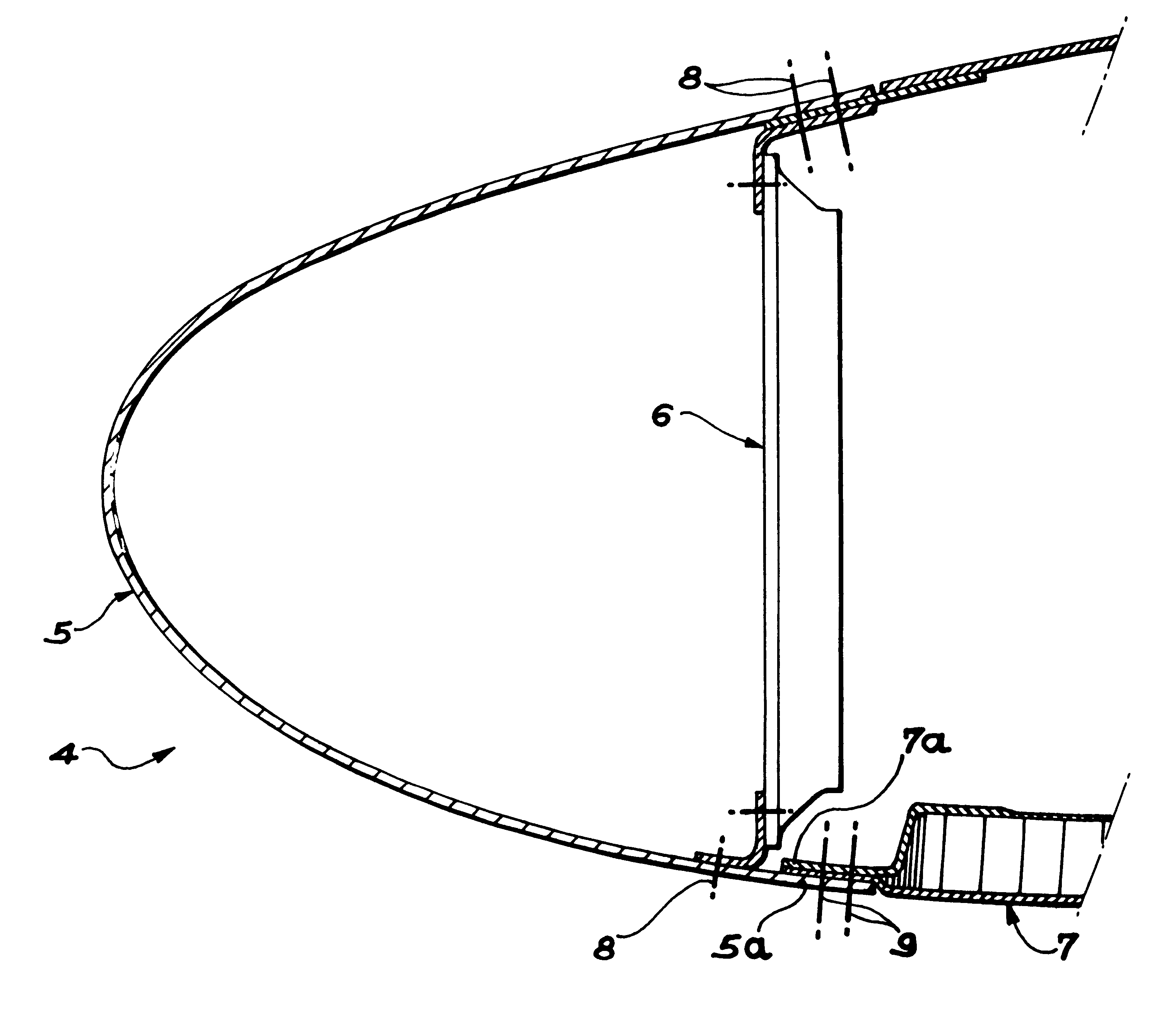
In the invention, the front part of the acoustic panel is placed in the extension of an internal, rear part of the reinforcing frame and the internal, rear part of the air intake lip is fixed on the one hand to the rear, internal part of the reinforcing frame and on the other hand to the front part of the acoustic panel by second fixing means.
In this case, the first fixing means advantageously comprise a plurality of linking or joining parts, which are circumferentially distributed about a longitudinal axis of the engine and overlap the rear, internal part of the front reinforcing frame and the front part of the acoustic panel within the structure. The first fixing means also comprise fixing members, such as rivets, linking the linking parts on the hand to the rear, internal part of the front reinforcing frame and on the other hand to the front part of the acoustic panel.
In order to compensate a possible thickness difference, shims, which are also traversed by the fixing members, ca...
second embodiment
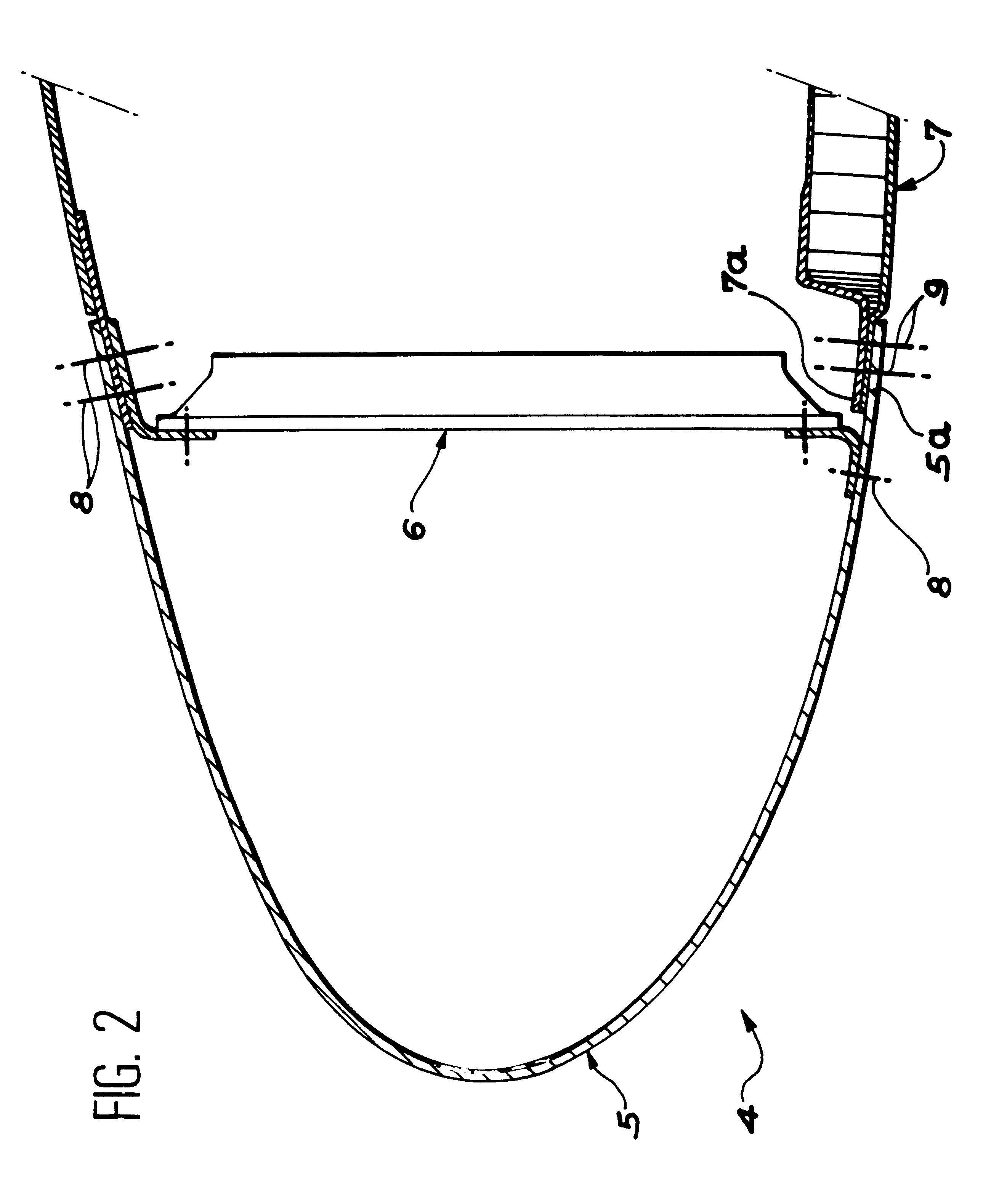
This second embodiment of the invention essentially differs from the first by the fact that instead of being placed in the extension of the rear, internal part 16a of the frame 16, the front part 17a of the acoustic panel 17 is displaced towards the interior of the structure with respect to said part 16a.
More specifically, in the variants of FIGS. 6A and 6B, the front part 17a of the acoustic panel 17 is oriented substantially parallel to the rear, internal part 16a of the front reinforcing frame 16. Under these conditions, the first fixing means 19 linking the frame 16 to the panel 17 comprise two linking parts 30 and 32, both having the shape of a rectangular, circular extrusion.
In these two variants, a first cylindrical flange of the linking part 30 is fixed to the interior of the rear, internal part 16a of the frame 16 by fixing members such as rivets 34 and a first cylindrical flange of the linking part 32 is fixed to the interior of the front part 17a of the panel 17 by fixing...
PUM
 Abstract
Description
Claims
Application Information