Method of and structure for connecting electric wire and connecting terminal

a technology of connecting terminal and electric wire, which is applied in the direction of connection contact material, connection effected by permanent deformation, line/current collector details, etc., can solve the problems of reducing productivity, difficult to integrate soldering operation into continuous automation lines, and corroding of core wire portions of wir

Inactive Publication Date: 2002-01-01
YAZAKI CORP
View PDF13 Cites 98 Cited by
  • Summary
  • Abstract
  • Description
  • Claims
  • Application Information

AI Technical Summary

Problems solved by technology

There has been a problem in that the core wire portions of the wire become corroded.
In addition, since the soldering operation is difficult to ...

Method used


Image

  • Method of and structure for connecting electric wire and connecting terminal
  • Method of and structure for connecting electric wire and connecting terminal
  • Method of and structure for connecting electric wire and connecting terminal

Examples


first embodiment

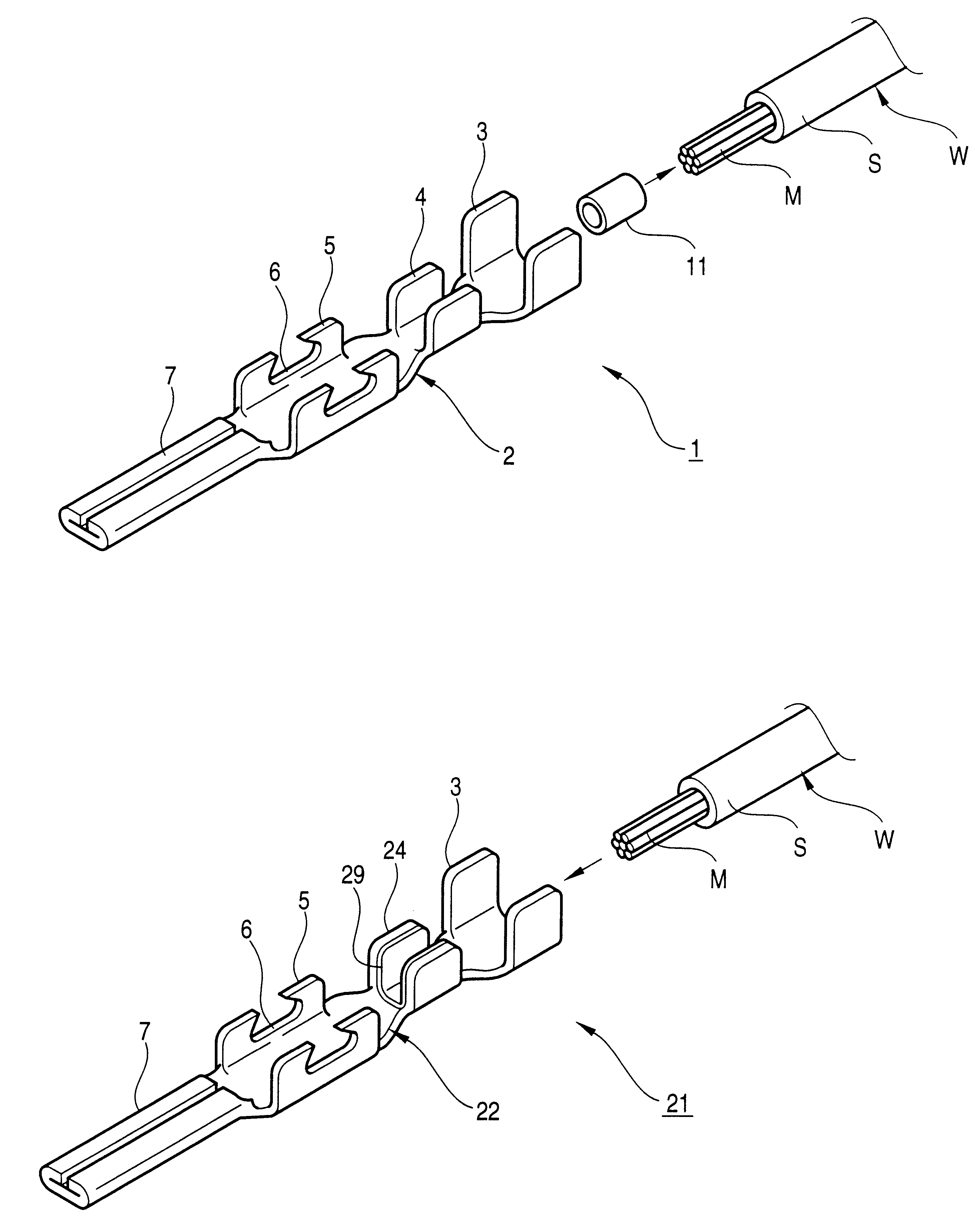
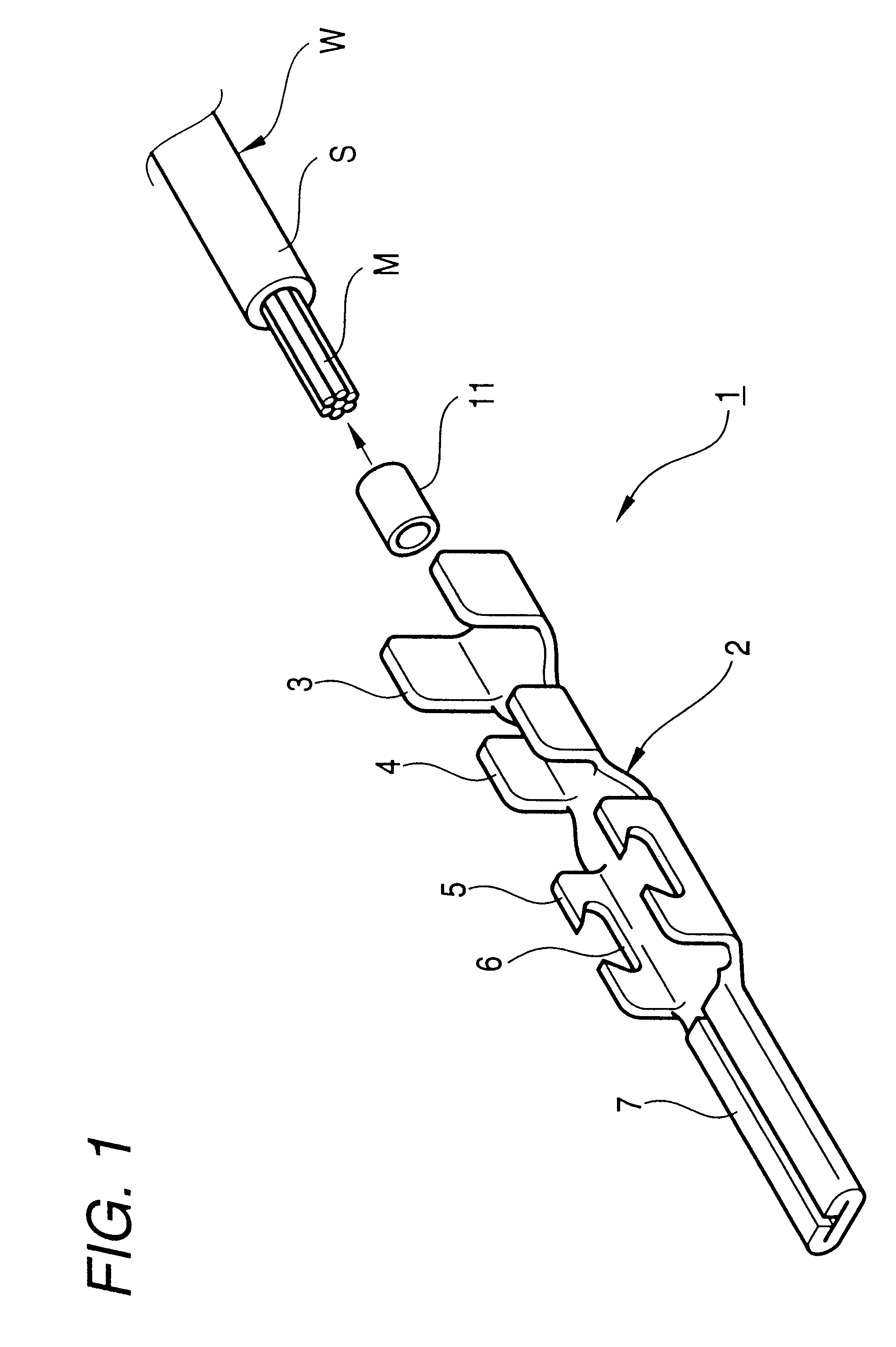
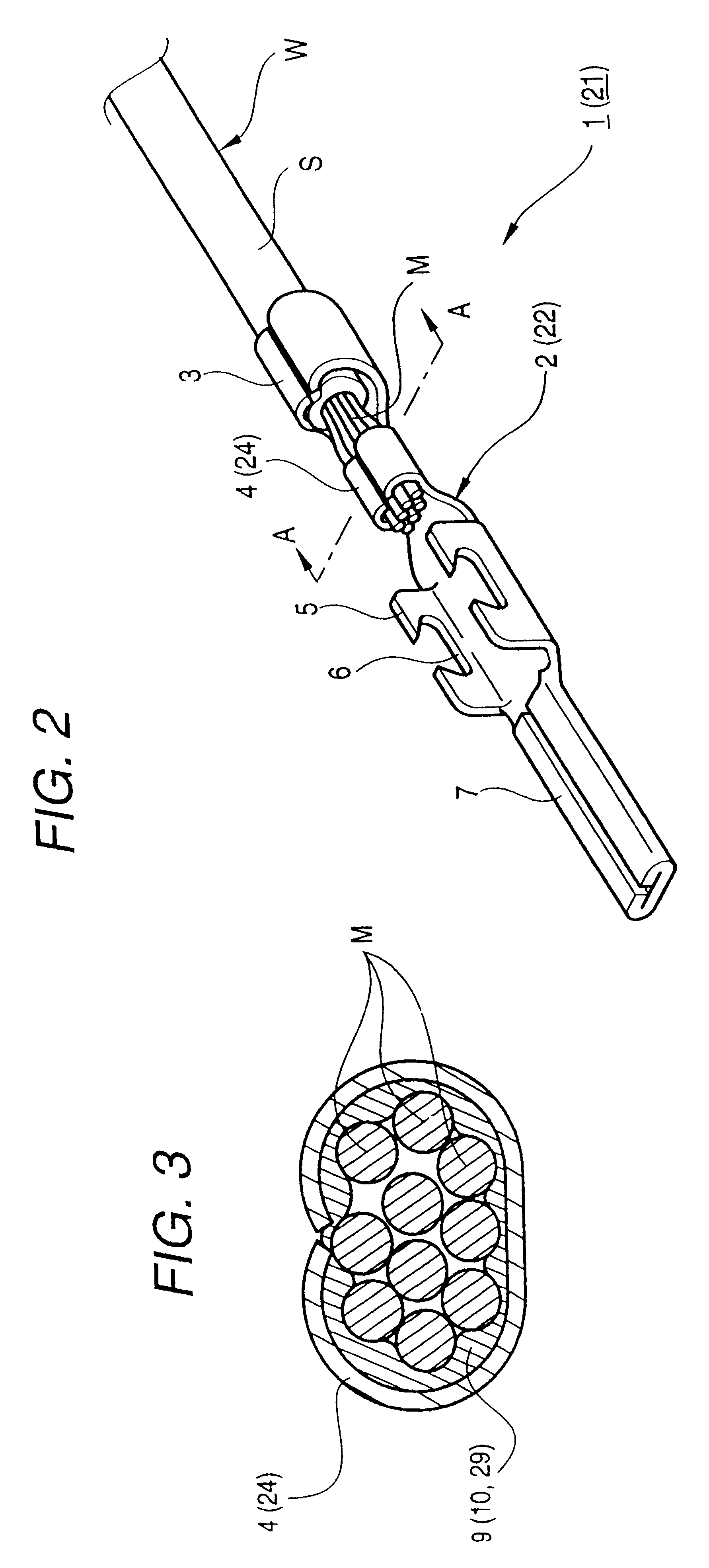
As shown in FIG. 1, a structure 1 for connecting an electric wire and a connecting terminal in accordance with the invention is a structure for caulking a crimp terminal in which core wire portions M exposed by stripping off an end portion of a sheathed wire W by a predetermined length, the core wire portion M are caulked by a conductor caulking portion 4 in the rear of a crimp terminal 2 and is connected. A tubular ring 9 is formed of a ductile metal, i.e., a soft metal having higher ductility than the material of the crimp terminal 2, e.g., gold, silver, lead, zinc, aluminum or the like. The tubular ring is interposed between an inner surface of the conductor caulking portion 4 and the core wire portions M in a state of being extended in the axial direction from the center of an end of the sheathed wire W.

More specifically, the core wire portions M are general a bundle of a plurality of slender copper wires, and the crimp terminal 2 is formed by press working by stamping out a pre...

third embodiment

Further, in the third embodiment, after the heating test the resistance of the crimped portion was even lower. This attributable to the fact that since a phenolic resin was used as the liquefied resin, the resistance of the conductor became small due to the reducing action of formaldehyde.

It should be noted that the invention is not limited to the above-described embodiments, and may be implemented by other embodiments by making appropriate modifications. For example, although both the crimp terminals 2 and 32 in the above-described embodiments were male terminals, the invention is applicable to female terminals as well.

In addition, although a description has been given of the tubular ring 9 in the first embodiment, the tubular ring 9 need not be a ring, and the invention is applicable to a semitubular shape formed by longitudinally splitting a tube along its axial direction.

As described above, in accordance with the method of connecting an electric wire and a connecting terminal ac...


PUM


Abstract

In a structure 21 for connecting an electric wire and a connecting terminal in the invention, a ductile metal film 29 is formed in advance on an inner surface of a conductor caulking portion 24 of a crimp terminal 22 by such as plating, vacuum deposition, or adhesion. Then, the conductor caulking portion 24 in the rear portion of the crimp terminal 22 is caulked onto core wire portions M in a state of being stripped and extended in the axial direction from an end of a sheathed wire W to thereby establish connection. Subsequently, the metal film 29 is fused on heating. Accordingly, the ductile metal film 29 enters gaps between the inner surface of the conductor caulking portion 24 and the core wire portions M and between adjacent ones of the core wire portions M by the caulking stress. Hence, the area of contact between the conductor caulking portion 24 and the core wire portions M via the metal film 29 increases, and conductivity improves, thereby making it possible to suppress heat generation.

Description

1. Technical Field to Which the Invention BelongsThe present invention relates to a method of and a structure for connecting an electric wire and a connecting terminal in which core wire portions of an electric wire are caulked by caulking portions of a connecting terminal so establish electrical connection.2. Related ArtVarious crimp terminals are known in which a conductor portion of an electric wire is caulked by caulking portions of a connecting terminal so establish electrical connection.As shown in FIG. 11, a tip portion of a sheath portion S of a sheathed wire W is stripped by a predetermined length, and core wire portions M are exposed in an axially extended state. In addition, a connecting terminal 51 is formed by stamping a metal plate. The connecting terminal 51 has in its rear portion a sheath caulking portion 52, a conductor caulking portion 53 and a positioning portion 54 with a pair of positioning grooves 55. The connecting terminal 51 has in its front portion a pin-s...

Claims


Application Information

Patent Timeline
IPC IPC(8): H01R4/10H01R4/18H01R4/02H01R43/04H01R43/048
CPCH01R4/187H01R4/024H01R43/048
Inventor USHIJIMA, HITOSHISAITO, YASUYUKI
Owner YAZAKI CORP
Why Eureka
Try Eureka