Carpenter hammer

a carpenter and hammer technology, applied in the field of carpenter hammers, can solve the problem of needing a hammer with specially shaped claws, and achieve the effect of easy removal

Inactive Publication Date: 2002-01-22
KOTSCHNER JOSEF +1
View PDF5 Cites 35 Cited by
  • Summary
  • Abstract
  • Description
  • Claims
  • Application Information

AI Technical Summary

Benefits of technology

The carpenter hammer of this invention is a drop forged tool steel device that includes a pair of claws, one of which is a shorter claw with a flat end and a longer pointed that allows bent nails to be easily removed especially in tight places. The striking face of the hammer is scored and beyond the region of the claws is a square configuration. The top of the hammer extending from the striking face contains a specially designed notch to seat a nail. A powerful magnet is embedded just below the notch to contain the nail while it is being driven into a desired object.

Problems solved by technology

The art illustrated above two problems extant in the industry, namely the need for a hammer with specially shaped claws that can extract nails in inaccesible or hard to position areas.

Method used


Image

  • Carpenter hammer
  • Carpenter hammer
  • Carpenter hammer

Examples


Embodiment Construction

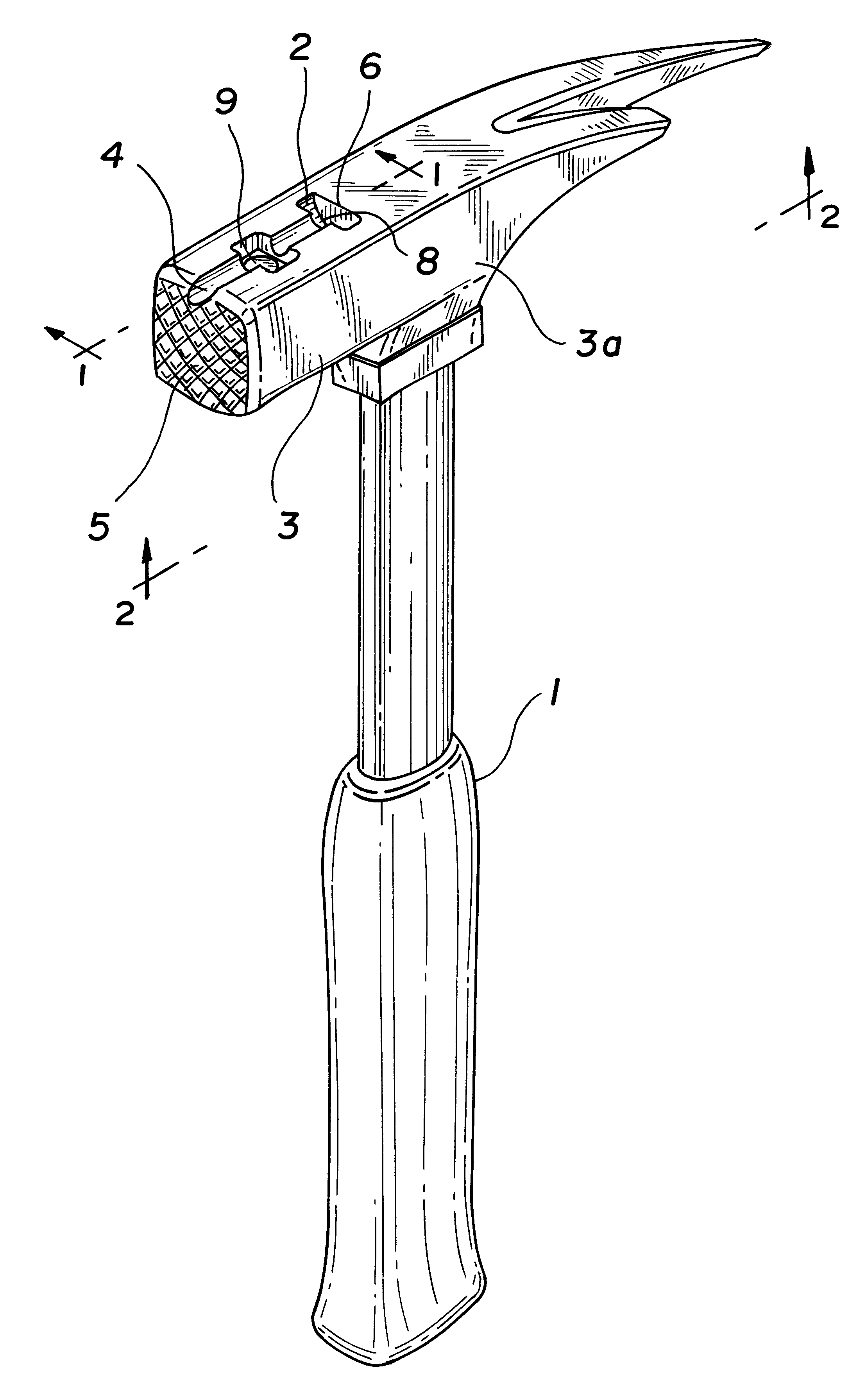
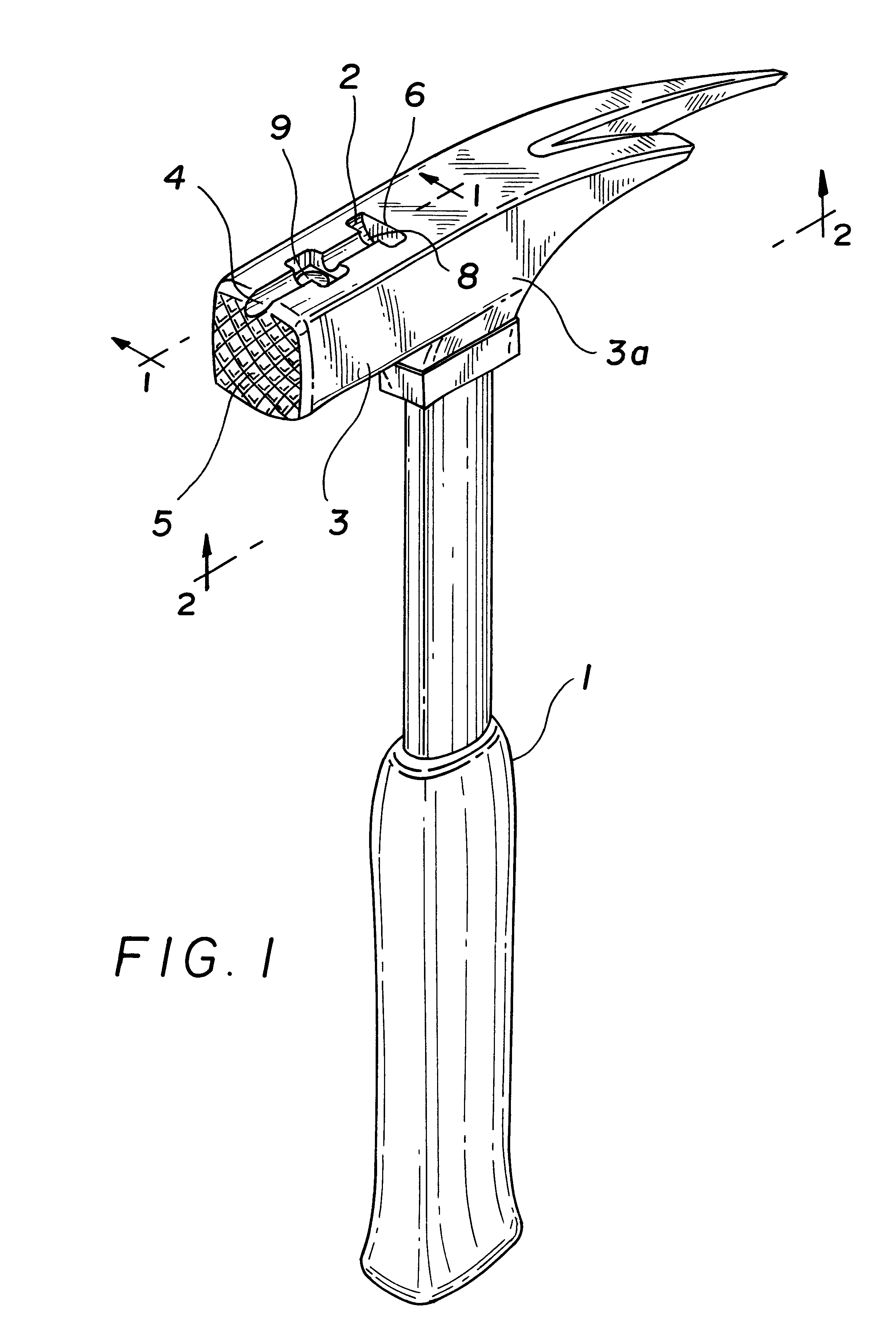
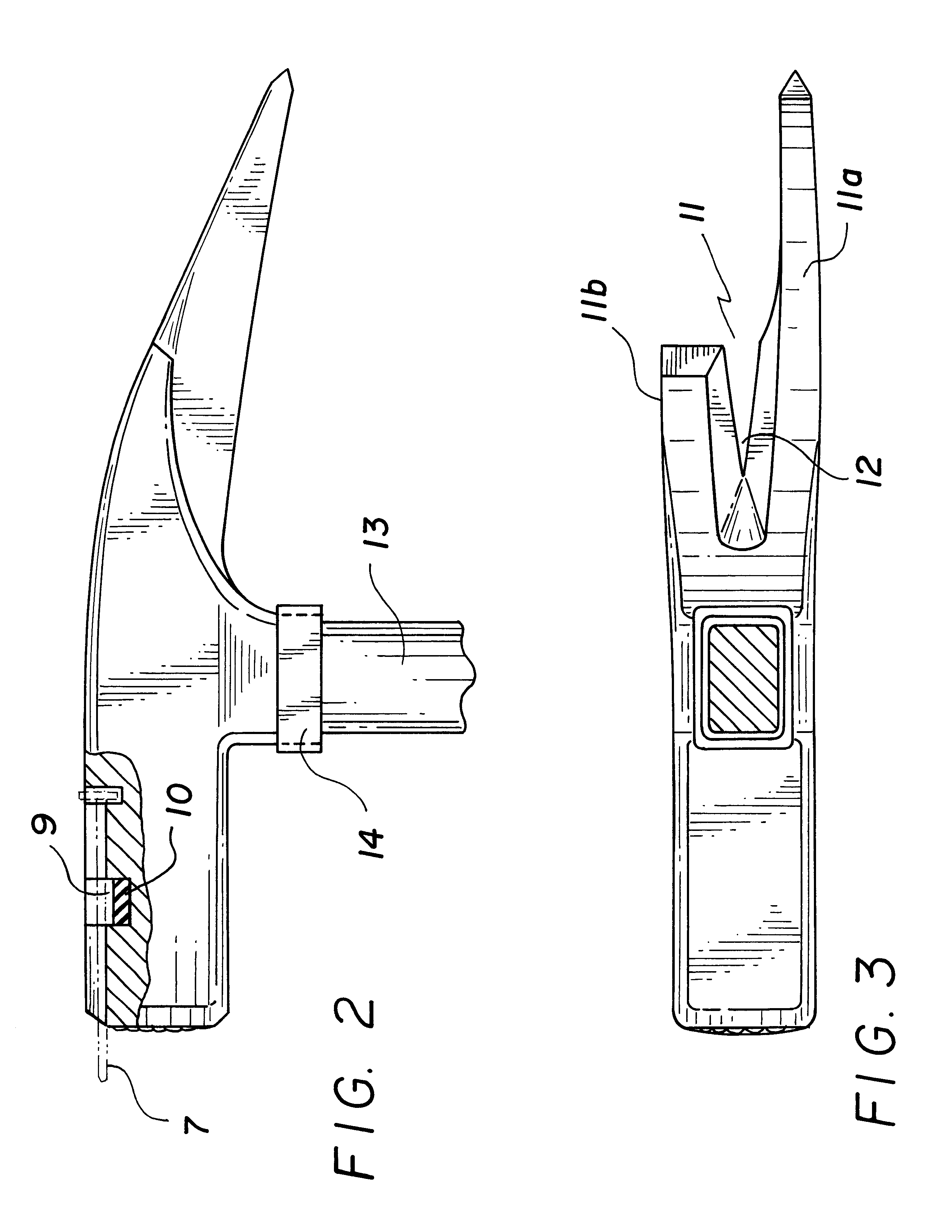
FIG. 1 shows a hammer 1 with a square head having a T-shaped notch 2 in the top of the shank 3 midway of its sides 3a. The notch portion 4, that is in a plane parallel to the top surface of the shank is semicircular and starts from a scored face 5, extending inwardly to such a distance as to accommodate the different size nails. The notch portion terminates in a transverse section 6 that is somewhat greater in depth than the notch to allow for the head of a nail 7. The head of the nail abuts firmly against the wall 8 of the shank adjacent the transverse section while the shank of the nail is firmly aligned in the notch. In the center of the length of the notch and below thereof is a cavity 9 wider than the notch and circular in shape. A disk like permanent magnet 10 is placed within this cavity so that its upper surface is about flush with lower surface of the nail. The magnet preferably used is known by the .TM. "Magnequench" and is an alloy of neodymium, iron and boron. These elem...


PUM


Abstract

A hammerhead made of tool steel and having in combination a pair of asymmetric claws and a magnetic nail holder, the holder being in the form of a T-shaped notch and a permanent magnet having a very high field intensity as compared to the conventional permannet magnet.

Description

FIELD OF INVENTIONThis invention pertains to a Carpenter Hammer and in particular to a unique combination involving the claws and the shank.BACKGROUND OF THE INVENTIONU.S. Pat. No. 611,793 teaches a combination tool that includes a hammer and a tong or vise. The hammer has a rounded head that includes a pair of claws, one of which terminates in a flat, sharp end and the other claw is pointed and extends beyond the end of the first claw. The sharp end is adapted to be forced under the head of a nail, spike or any other object to be moved. The sharp end can be forced into wood or under any other objects.U.S. Pat. No. 1,110,188 is another round headed hammer where a slot that defines the claw extends diagonally of the head opening at one side thereof to provide relatively short and long members. The long member hasd a borad end that provides a cutting edge, the shorter member terminates rearwardly of the plane of the cutting edge so as not to interfere with material being cut.U.S. Pat....

Claims


Application Information

Patent Timeline
Patent Type & Authority Patents(United States)
IPC IPC(8): B25D1/06B25D1/00
CPCB25D1/06
Inventor KOTSCHNER, JOSEFKOTSCHNER, RALPH-PAUL
Owner KOTSCHNER JOSEF
Why Eureka
Try Eureka