Positioning stage

a technology of positioning stage and feeding mechanism, which is applied in the field of positioning stage, can solve the problems of insufficient fine adjustment of feed of the table, small curvature of the belt around the belt, and difficulty in simplifying the structure of the feeding mechanism and reducing a siz

Inactive Publication Date: 2002-01-22
MITUTOYO CORP
View PDF7 Cites 2 Cited by
  • Summary
  • Abstract
  • Description
  • Claims
  • Application Information

AI Technical Summary

Benefits of technology

According to the above arrangement, the drive force transmission member is driven not by the pulley portion but by the pinch mechanism separately provided (a combination of a rotation drive capstan and a pinch roller rotating by being pressed). The pinch mechanism holds the drive force transmission member (belt, wire, chain and other flexible elongated member) to secure transmission of the drive force. Accordingly the strong tension of the drive force transmission member necessary for transmitting the rotation of the pulley to the drive force transmission member is not required, thus size-reducing and simplifying the portion adjacent to the pulley.
Accordingly, an appropriate holding force is applied to the respective manipulation knobs so that an unprepared movement of the stage caused by vibration etc. can be prevented and an appropriate weight is applied to a minute operation of the stage, thereby facilitating minute operation control.

Problems solved by technology

However, on account of problem relating to accuracy and movement smoothness, another type of feeding mechanism using a belt and a pulley recently comes into use (see Japanese Patent Publication No.
According to the above-described conventional feeding mechanism by the belt and the pulley, following problems arise.
First, it is difficult to simplify the structure of the feeding mechanism and to reduce a size thereof.
Second, feed of the table cannot be adjusted finely enough.
However, when the radius of the pulley is reduced, curvature of the belt wound therearound becomes small.
Accordingly, the radius of the pulley cannot be reduced beyond the allowable minimum bend radius, thus unable to sufficiently set the minute feed of the table.
Third, the components cannot be arranged freely enough.
Operability of the manipulation knob is not so good because the pulley is ordinarily disposed at both ends of the stretched belt (end of the feeding mechanism).
However, as described above, since the location is restricted by the position of the pulley, it cannot be easily changed.
Though the position can be changed using other transmission means, the mechanism can be so complicated.
More specifically, the feeding mechanism can only be disposed at a periphery of respective tables and the space at central portion cannot be used.

Method used


Image

  • Positioning stage
  • Positioning stage
  • Positioning stage

Examples


Embodiment Construction

)

An embodiment of the present invention will be described below with reference to drawings.

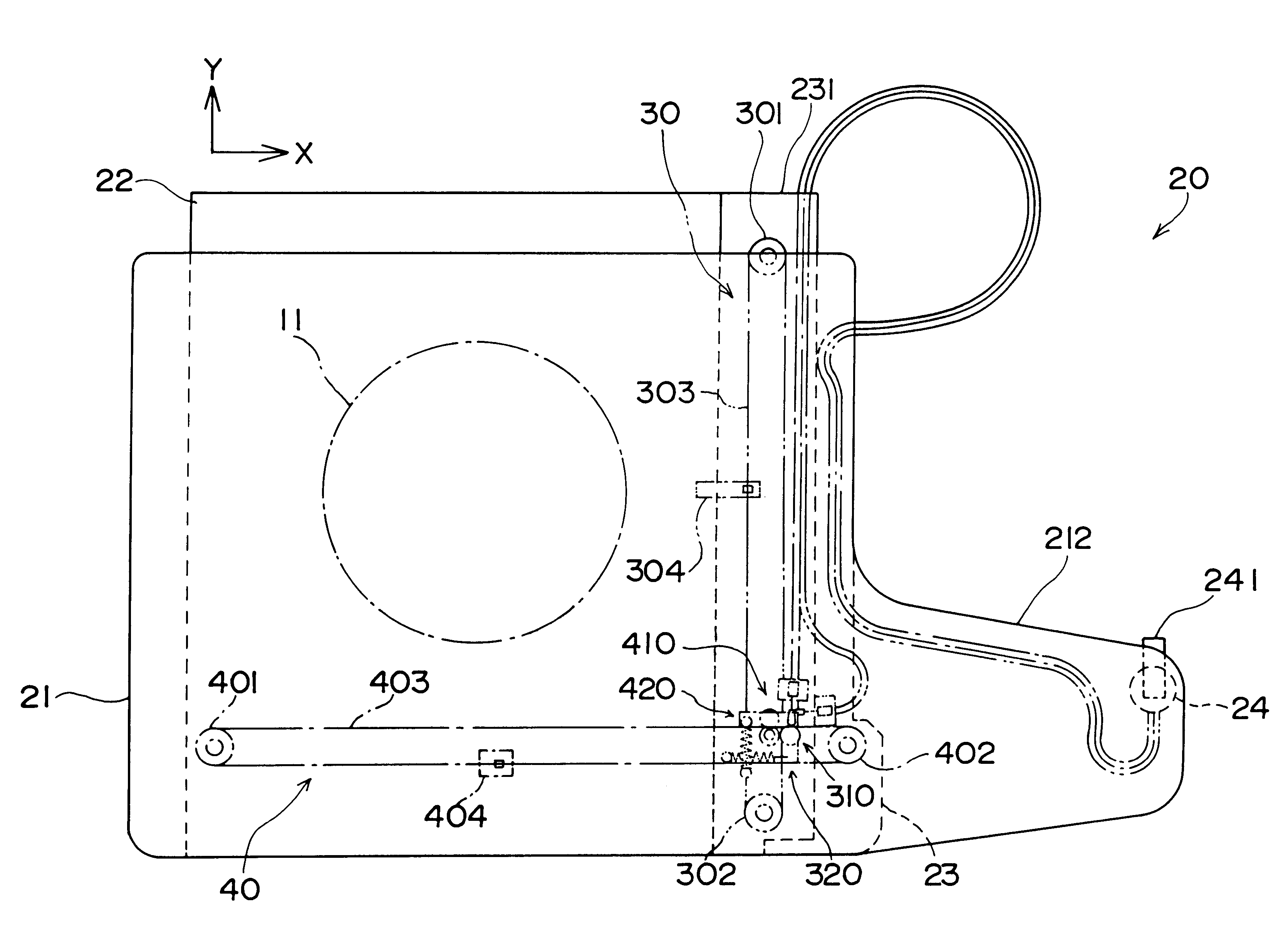
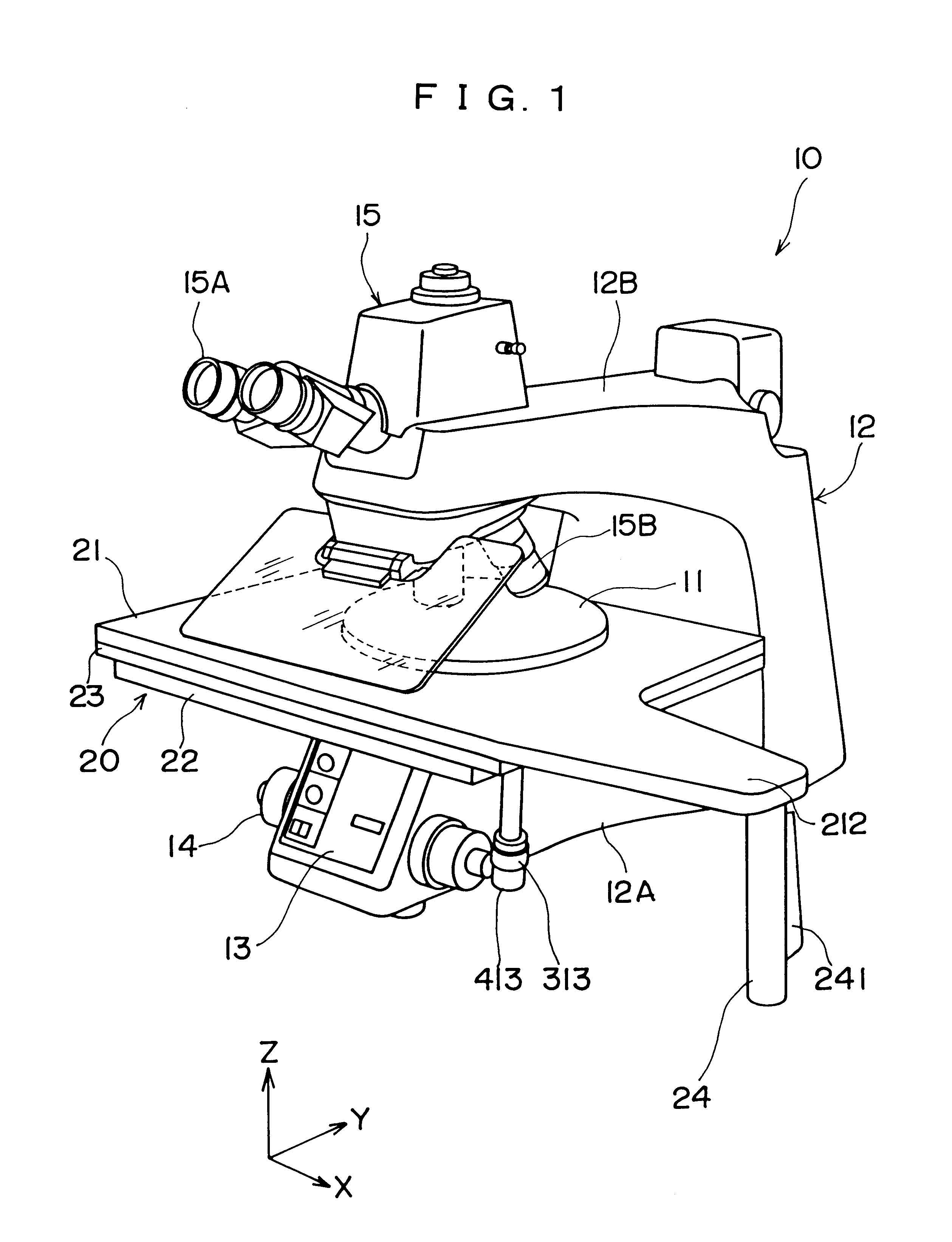
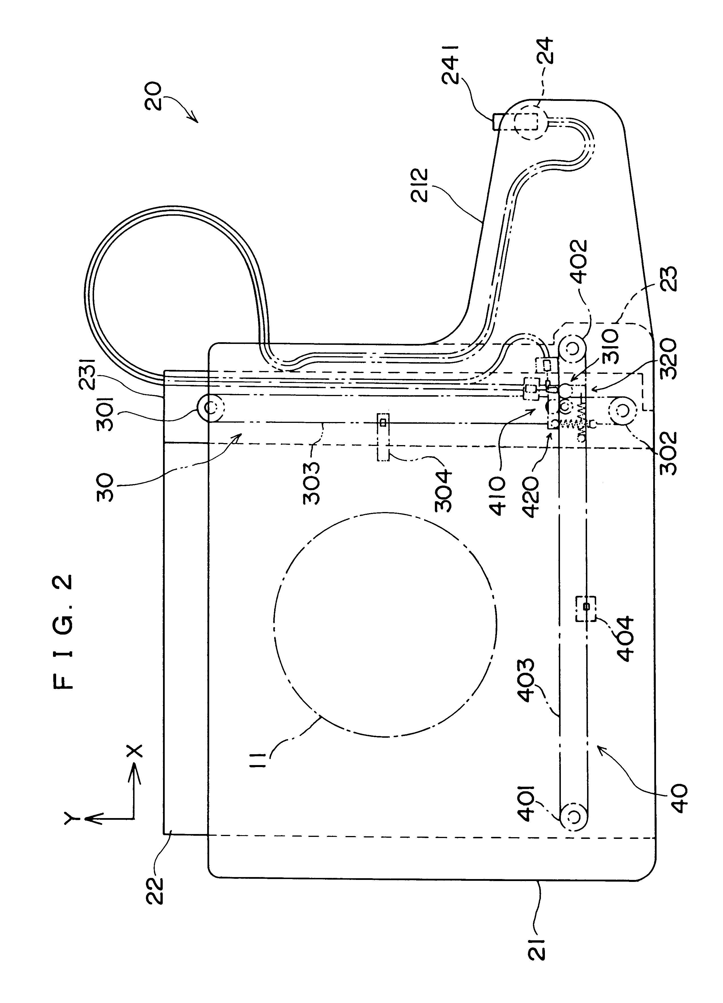
In FIG. 1, a microscope 10 is for detecting surface of a silicon wafer 11 to be measured, and a positioning stage 20 according to the present invention is arranged on a part of the microscope 10 for the wafer 11 to be rested.

The microscope 10 has a body 12 having C-shaped side configuration.

The positioning stage 20 is elevatably provided to a lower portion 12A of the body 12 and the wafer 11 rests on a table 21 formed on an upper side of the positioning stage 20. A control panel 13 including a function switch for illumination etc. is disposed on a front side of the lower portion 12A and an elevation knob 14 for elevating (moving along Z-axis) the positioning stage 20 is provided on a side of the lower portion 12A.

An upper portion 12B of the body 12 is formed to stretch over the table 21, and an optical mechanism 15 is provided at a distal end thereof. The optical mechanism 15 has an eyepiece 1...


PUM


Abstract

A feeding mechanism for moving a table relative to a base has a pair of pulley (301, 302, 401, 402) supported by either one of the table (21) and the base (22), a loop-shaped belt (303, 403) stretched between the pulleys and having a part thereof extending in a movement direction of the relative movement, a joint (304, 404) for connecting the other one of the table and the base with the belt, and a pinch mechanism (310, 410) provided to the either one of the table and the base to hold a part of the belt.

Description

1. Field of the InventionThe present invention relates to a positioning stage. More specifically, it relates to a mechanism for an accurate movement control while resting a workpiece thereon during accurate measurement by microscope inspection, optical measurement etc.2. Description of Related ArtConventionally, during microscope inspection etc., a workpiece is put on a cross-travel stage and is moved so that a portion of interest comes within a predetermined measurement area located on an extension of an objective. For measurement, the portion of interest has to be accurately moved little by little.In view of the above requirement, the portion of the stage for the workpiece to be put on is arranged to be movable in X and Y directions and a driving mechanism capable of accurate feeding movement little by little is provided to control movement thereof.For such driving mechanism of the stage, a rack-and-pinion mechanism and a feeding mechanism using a rail and a friction gear can be u...

Claims


Application Information

Patent Timeline
Patent Type & Authority Patents(United States)
IPC IPC(8): G01B5/00G02B21/26G02B21/24
CPCG02B21/26G01B5/0002
Inventor TANAKA, SHOICHISANO, HIDEKAZU
Owner MITUTOYO CORP
Why Eureka
Try Eureka