Surgical instrument

Inactive Publication Date: 2006-09-12
KARL STORZ GMBH & CO KG
View PDF2 Cites 99 Cited by
  • Summary
  • Abstract
  • Description
  • Claims
  • Application Information

AI Technical Summary

Benefits of technology

[0019]An additional independent aspect of the invention concerns a tube (e.g. the inner tube mentioned above in connection with the instrument) having a rigid proximal region and a flexible region disposed distally with respect to the rigid proximal region. The flexible region of the tube has a slit in its wall which, as viewed in the longitudinal direction of the tube, winds in a helical fashion about the longitudinal axis of the tube and meanders with respect to this helical

Problems solved by technology

The teeth and the recesses are shaped in such a fashion that

Method used


Image

  • Surgical instrument
  • Surgical instrument
  • Surgical instrument

Examples


Example

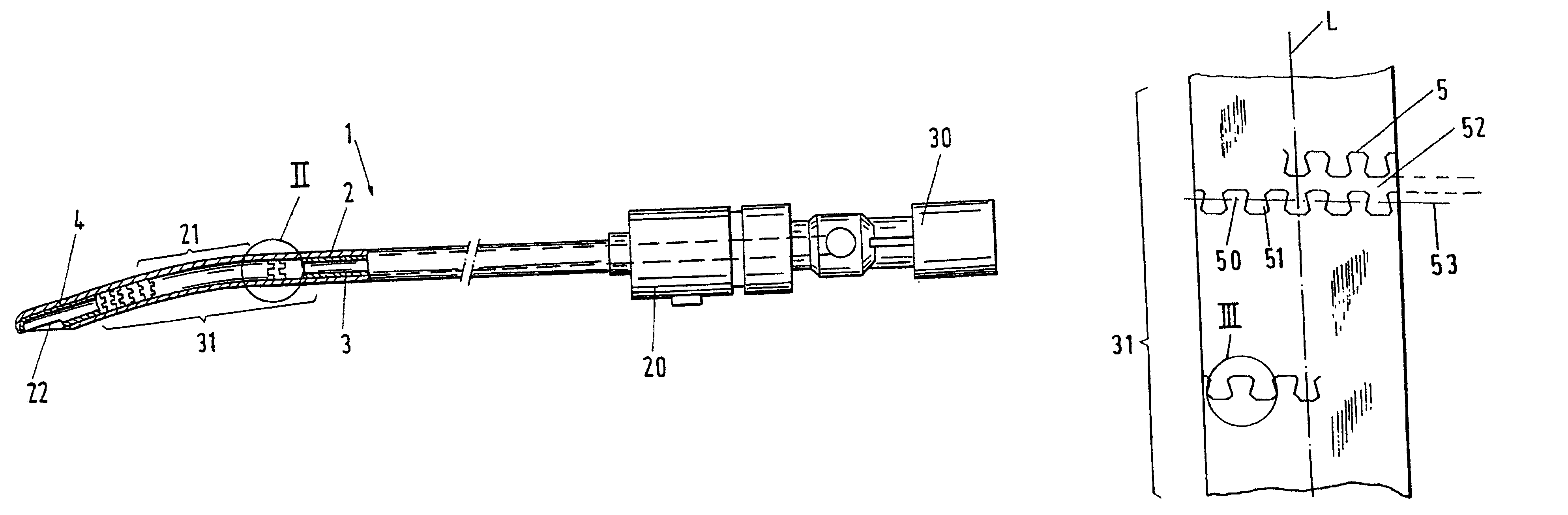
[0029]FIG. 1 shows an embodiment of a surgical instrument 1 in accordance with the invention. The instrument 1 clearly comprises an outer tube 2 in which an inner tube 3 is disposed for rotation. The surgical instrument 1 can be accepted by a handle (not shown) in which a rotating drive, e.g. an electrical motor, can be provided for rotational drive of the inner tube 3. The proximal end of the inner tube is firmly connected to a coupling member 30 for coupling to the rotating drive by bringing the coupling member 30 into engagement therewith. The proximal end of the outer tube 2 is firmly connected to a locking member 20 which, in turn, can be accepted by and locked within the handle (not shown). The coupling member 30 and the inner tube 3 connected thereto can be rotated relative to the locking member 20 and relative to the outer tube 2 connected thereto.

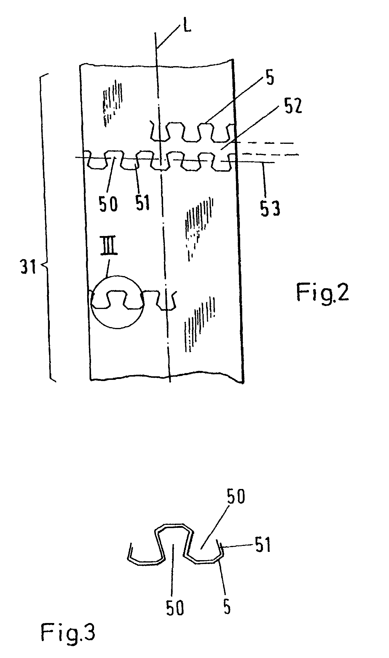
[0030]The proximal region of the inner tube extends in a rigid manner from the proximal end region towards a flexible region 31. ...


PUM


Abstract

A surgical instrument (1) for the removal of tissue comprises an outer tube (2) having an opening (22) for the removal of tissue, fashioned in a distal region, preferentially in the vicinity of the distal end of the outer tube (2). It further comprises an inner tube (3) disposed in the outer tube (2) and having a rigid proximal region for transferring forces or momenta acting on this proximal region to a distal region of the inner tube (3), preferentially to the distal end of the inner tube (3). The instrument further comprises a cutting tool (4) disposed at the distal region of the inner tube (3), preferentially at the distal end of the inner tube (3), for facilitating cutting of tissue which is subjected to the action of the cutting tool (4) in the vicinity of the opening (22) in the distal region of the outer tube (2), wherein the inner tube (3) has a flexible region (31) located between its rigid proximal region and the cutting tool (4). The inner tube (3) has a slit (5, 5a) in its wall in the flexible region (31) which, as viewed in the longitudinal direction of the inner tube (3) winds in a helical fashion about the longitudinal axis (L) of the inner tube (3) and meanders back and forth with respect to this helical line (52, 52a).

Description

[0001]This is a continuation of application number 09 / 621,870 filed Sep. 15, 1999 now abandoned and also claims Paris Convention priority of EP 98 810 930.2 filed Sep. 17, 1998 the entire disclosure of which are hereby incorporated by reference.BACKGROUND OF THE INVENTION[0002]The invention concerns a surgical instrument for the removal of tissue, comprising an outer tube having an opening, for accepting tissue, in a distal region, preferentially in the vicinity of the distal end of the outer tube and with an inner tube disposed within the outer tube and having a rigid proximal region for transmitting forces or momenta acting on this proximal region to a distal region of the inner tube, preferentially to the distal end of the inner tube, and also with a cutting tool disposed at the distal region of the inner tube, preferentially on the distal end of the inner tube, for cutting tissue subjected to the influence of the cutting tool in the vicinity of the opening of the distal region o...

Claims


Application Information

Patent Timeline
IPC IPC(8): A61B17/22A61B17/28A61B17/32F16C1/02
CPCA61B17/32002F16C1/02A61B2017/2905F16C2316/10
Inventor HILTEBRANDT, SIEGFRIED
Owner KARL STORZ GMBH & CO KG
Why Eureka
Try Eureka