
Self-charging electric vehicles and aircraft, and wireless energy distribution system

a self-charging, electric vehicle technology, applied in the direction of battery/fuel cell control arrangement, light to electrical conversion, propulsion by batteries/cells, etc., can solve the problems of system impracticality, small energy generation, and sometimes larger harvesting mechanisms, so as to increase transmission distance, increase transmission efficiency, and extend the range

Inactive Publication Date: 2014-11-18
GOVERNING DYNAMICS INVESTMENT +1
View PDF16 Cites 104 Cited by
  • Summary
  • Abstract
  • Description
  • Claims
  • Application Information

AI Technical Summary

Benefits of technology

This patent describes a system and method that uses wireless technology to quickly collect and store electrical energy from magnetic resonance. This energy is then used to power vehicles, extending their range and ensuring continuous operation. The system is designed to be efficient, with a higher transmission efficiency and greater transmission distance than conventional systems. In addition, security measures are implemented to prevent unauthorized use of the system. Overall, this system improves efficiency and security of wireless energy transmission for electric vehicles.

Problems solved by technology

The constraint here is that very little energy is generated and the harvesting mechanisms are sometimes larger than the devices they are designed to power.
However, such systems are impractical, because they are limited in their portability, for example, boarding an aircraft with a full-fledged fuel cell in a laptop.
However, most of the energy is lost before reaching the receiver and the power that does reach the receiver is extremely low.
However, this technique is still rather experimental, and operates based on principles of resonance.
However, as in the radiative method, the energy can travel only a distance of a few meters.
However, while there are vehicles that can be recharged, these vehicles do not permit recharging during motion, and require a cable attachment to the vehicle and a long charge time.
As a result, these types of vehicles can only cover short distances.

Method used


Image

  • Self-charging electric vehicles and aircraft, and wireless energy distribution system
  • Self-charging electric vehicles and aircraft, and wireless energy distribution system
  • Self-charging electric vehicles and aircraft, and wireless energy distribution system

Examples


Embodiment Construction

[0031]Disclosed is a method and system for efficient distribution of power using wireless means, and a system and method for wireless power distribution to provide electric vehicles with a way to continuously and wirelessly collect, use and charge their power systems and thereby use the transmitted power to effect movement.

[0032]In accordance with the invention, a system and method are provided that allows a hybrid, simplified and less costly solution for charging and providing a way for vehicles (or mobile devices) to continuously move while consuming, charging / recharging.

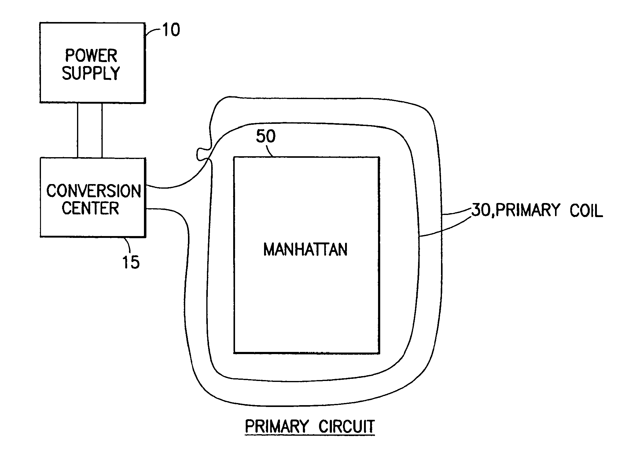
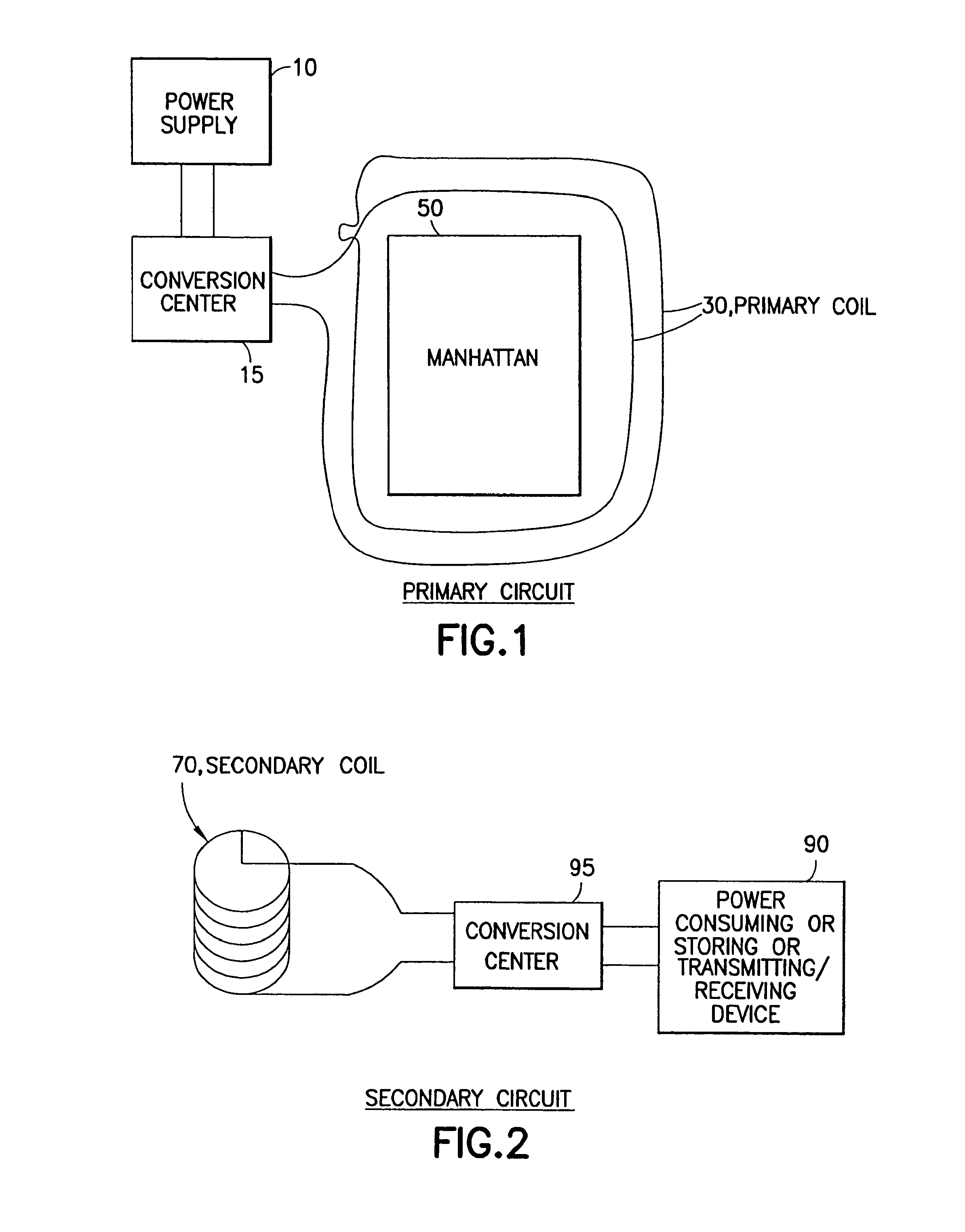
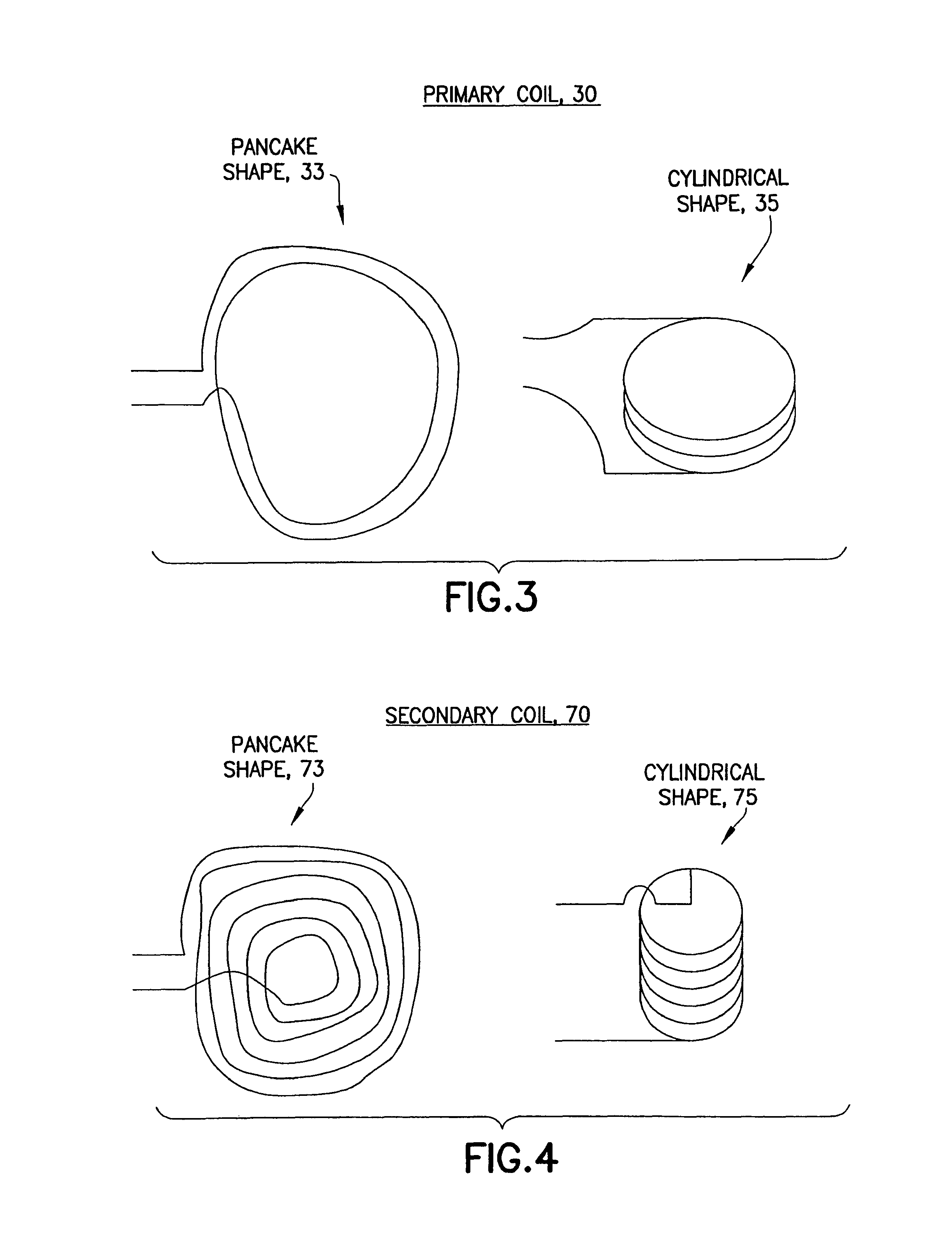
[0033]In one embodiment, the power transfer can take place via multiple known ways. One is similar to ways known in the art as inductive transfer of electromagnetically coupled resonating circuits. FIG. 1 is an illustration of a primary circuit of the power distribution system in accordance with an exemplary embodiment of the invention, where the primary circuit comprises a circuit that contains a primary coil and...


PUM


Abstract

A method and system for efficient distribution of power using wireless means, and a system and method for wireless power distribution to provide electric devices, such as vehicles with a way to continuously and wirelessly collect, use and charge their power systems and thereby use the transmitted power for operation. The system and method allows a hybrid, simplified and less costly way to charge devices, such as vehicles so that the devices continuously operate while charging / recharging.

Description

RELATED APPLICATIONS[0001]This is a U.S. national stage of application No. PCT / US08 / 11204, filed on Sep. 26, 2008. Priority is claimed on the following applications: U.S. Provisional Application No. 60 / 995,396 Filed on Sep. 26, 2007; U.S. Provisional Application No. 60 / 998,064 Filed on Oct. 5, 2007, the content of which are incorporated here by reference.BACKGROUND OF THE INVENTION[0002]1. Field of the Invention[0003]The present invention generally relates to the field of power transmission and, more particularly, to a method and system for efficient distribution of power using wireless means, and a system and method for wirelessly distributing power to provide electrical vehicles with a way to continuously, wirelessly charge their power systems and thereby use the transmitted power for motion.[0004]2. Description of the Related Art[0005]The amount of energy a battery can store per unit volume is presently increasing by about 8% a year. Yet, the needs of ever more powerful electroni...

Claims


Application Information

Patent Timeline
Patent Type & Authority Patents(United States)
IPC IPC(8): H02J7/02H02J7/00B60L11/18H02J5/00H02J7/14
CPCY02T90/14B60L11/1831B60L11/182H02J5/005B60L11/185Y02T90/12Y02T10/7005B60L11/1842Y02T90/122H02J7/025Y02T90/125H02J7/0027B60L11/1838Y02T10/7088Y02T90/121Y02T10/7072B60L50/53B60L53/12B60L53/39B60L55/00B60L53/665B60L53/11B60L58/21B60L53/51B60L53/52B60L53/66B60L58/15Y02T90/16Y02T10/70H02J50/12H02J50/90B60L7/12B60L8/003B60L2200/10
Inventor MASHINSKY, ALEX
Owner GOVERNING DYNAMICS INVESTMENT
Learn More