Molding system using film heaters and/or sensors

a technology of film heaters and sensors, which is applied in the field of molding system using film heaters and/or sensors, can solve the problems of large waste of heat generated by heaters, relatively inefficient heating arrangements, and time-consuming and costly manufacturing of spiral grooves

Inactive Publication Date: 2002-01-29
HUSKY INJECTION MOLDING SYST LTD
View PDF72 Cites 59 Cited by
  • Summary
  • Abstract
  • Description
  • Claims
  • Application Information

AI Technical Summary

Problems solved by technology

Temperature control issues are also very important when molding certain thermally sensitive materials such as PET in a multicavity mold or when molding articles made of different materials that are injected through a single hot runner nozzle.
However, as is typical of such prior art manifold heating apparatus a significant proportion of the heat generated by the heaters is wasted heating the entire manifold block rater than directly heating the resin flowing in a melt channel contained therein.
However, the disclosed heater heats both the hot runner nozzle body and the melt channel contained therein, a relatively inefficient heating arrangement.
Additionally, manufacturing the spiral groove and assembling the heater therein is time-consuming and costly.
The foregoing problems with prior art heaters are particularly evident in coinjection and multiinjection mold manifolds and hot runner nozzles.
Second, the heat supplied to each channel cannot be varied according to the size of each channel and the Theological characteristics of the resin flowing therein.
However, the heater disclosed in Hiroyoshi has several significant drawbacks that militate against its application to a mold manifold or hot runner nozzle.
First, the Hiroyoshi heater is not removable and thus requires replacement of the entire element when the heater bums out.
Second, the heater inefficiently heats the entire machine nozzle body rather than directly heating the molten resin.
Third, the healer cannot provide a profiled temperature gradient across the flow of molten resin, an important feature for managing shear stress in the flow of molten resin.
U.S. Pat. No. 5,504,304 discloses a removable ceramic heater made of a ceramic paste whose thickness is hard to control.
Such heaters as these do not provide for intimate contact with the nozzle body or the nozzle tip and thus reduce heat transfer and increase heat loss.

Method used


Image

  • Molding system using film heaters and/or sensors
  • Molding system using film heaters and/or sensors
  • Molding system using film heaters and/or sensors

Examples


Embodiment Construction

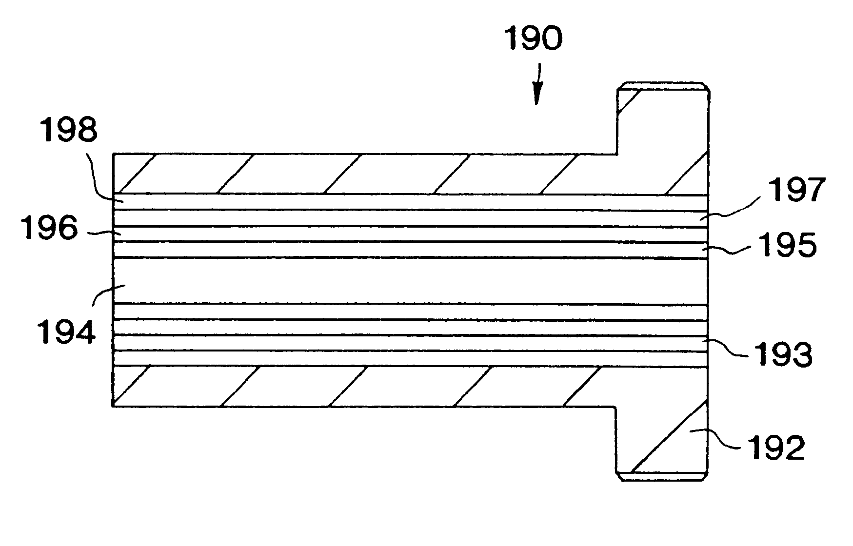
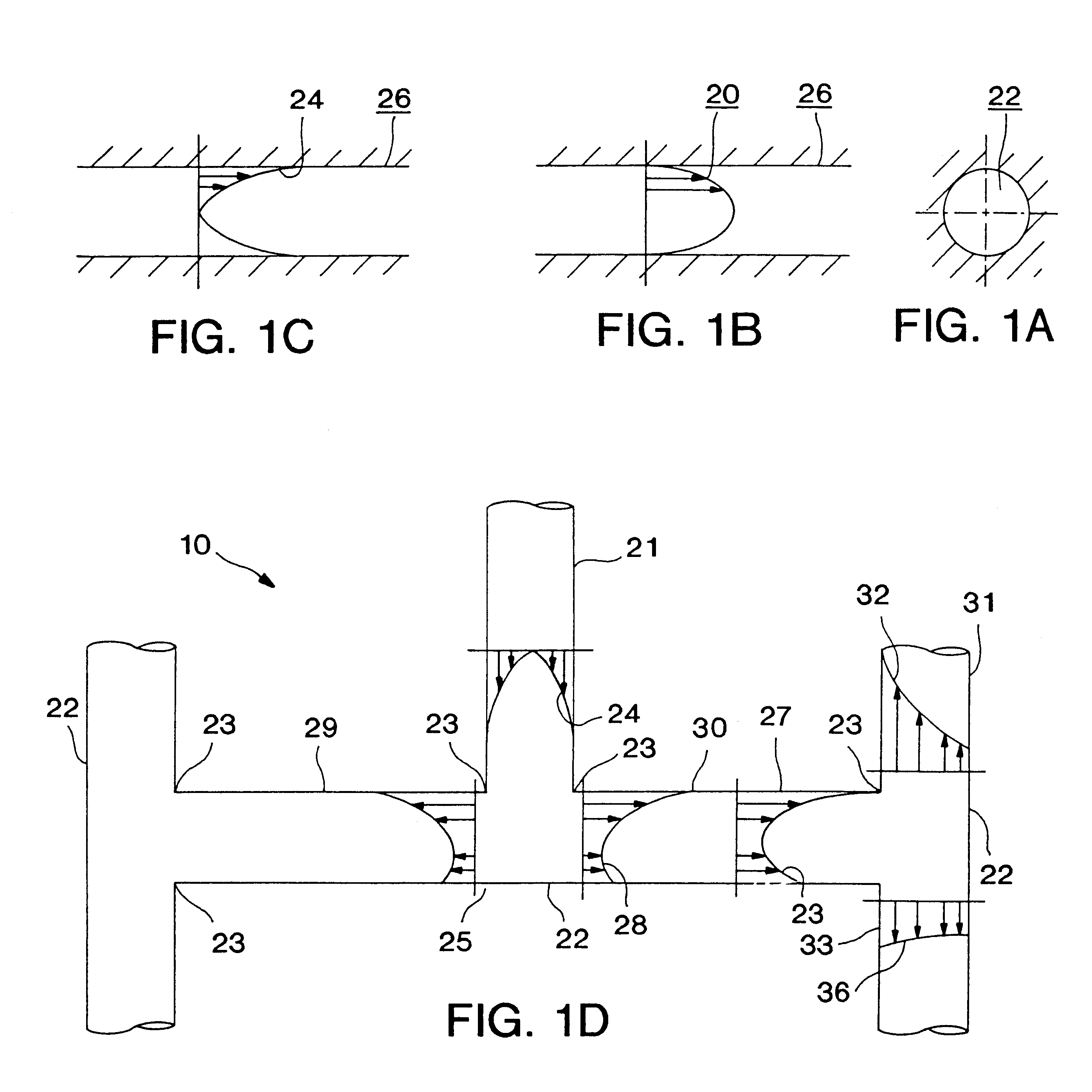
The present embodiments locate compact active and / or passive film elements along a melt channel from, for example, a sprue bushing to a mold cavity space to improve heat and flow management there. The active elements, which may be fabricated using advanced thin film technologies, are compact, reliable, stable, and energy efficient. Advantageously, the active elements may be located near or in direct contact with a flow of molten resin. The active elements may be any of a thin film heater, thermistor, thermocouple, resistance temperature detector, pressure sensor, gas sensor, optical guide leakage sensor, or combinations and equivalents thereof. The passive elements, which also may be fabricated using thin film technologies, interact with the active elements and may be made of electrical and thermal insulative materials and / or wear resistant materials. Preferably, the passive elements are in direct contact with the flow of molten resin to improve the laminar flow thereof. Employing t...


PUM

PropertyMeasurementUnit
thicknessaaaaaaaaaa
thicknessaaaaaaaaaa
temperaturesaaaaaaaaaa

Abstract

Improved mold manifold and hot runner nozzle using thin film elements include at least one active or passive thin film element disposed along a melt channel between the manifold inlet and the hot runner nozzle. Preferably, the thin film element may comprise a thin film heater in direct contact with the molten resin and position to aid in the heat and flow management of the resin within the melt channel. Thin film temperature sensors, pressure sensors, and leak detectors may also be provided in the vicinity of the melt channel to enhance process control in the injection molding machine.

Description

1. Field of the InventionThe present invention relates to an improvement in heat management and process control for a molding process and, more particularly, to the use of active and / or passive film heating and / or sensing elements located along a flow channel of molten resin to a mold cavity space.2. Description of the Related ArtIn an injection molding process, it is important to maintain a resin in a molten state as it flows from a nozzle of an injection molding machine, through a mold sprue bushing, a mold manifold, a hot runner nozzle, and into a mold cavity space, where the resin cools to form an injection-molded article. Additionally, the shear stress profile of the flow of resin must be monitored and managed to insure proper filling of the cavity space. This is especially important in the area close to the mold gate because the temperature there is rapidly cycled between hot and cold conditions before the molded article is removed from the cavity. Temperature control issues a...

Claims


Application Information

Patent Timeline
Patent Type & Authority Patents(United States)
IPC IPC(8): B29C45/27B29C45/16B29C45/00B29C45/26B29C45/02
CPCB29C45/1603B29C45/2701B29C45/2711B29C45/2737B29C45/02B29K2067/00B29C2045/274B29C2045/2741B29C2045/2745B29C2045/2746B29C2045/2722B29C45/00
Inventor GODWIN, HAROLDOLARU, GEORGEWHIFFEN, DAVID
Owner HUSKY INJECTION MOLDING SYST LTD
Why Eureka
Try Eureka