
Printing with designation of processing

a processing and printing technology, applied in the direction of digital output to print units, visual presentation using printers, instruments, etc., can solve the problems of overrun, the number of primitive processing units needed to print complicated graphics becomes enormous, and the rasterization processing during parallel operation cannot keep up with the sending of print data

Inactive Publication Date: 2002-02-19
CANON KK
View PDF7 Cites 37 Cited by
  • Summary
  • Abstract
  • Description
  • Claims
  • Application Information

AI Technical Summary

Problems solved by technology

In a device which performs one page of printing by executing such band processing without possessing one page of bitmap memory, rasterization processing during parallel operation cannot keep up with the sending of print data when the image to be rendered is complicated or when the printing speed of the printer is high.
The same problem arises also in an apparatus which handles grayscale image data by allocated a plurality of bits to each pixel to realize grayscale representation.
However, since the units capable of being processed by hardware used to perform high-speed processing in this manner are primitive, the number of such primitive processing units needed to print complicated graphics becomes enormous.
As a result, there is the possibility that overrun will occur or that the quantity of intermediate codes will exceed the amount of image data to be generated.
If there is a large amount of processed data, rendering time is prolonged and, as a result, the risk of overrun occurs.
Such processing is complicated, however, and invites a decline in printer throughput.

Method used


Image

  • Printing with designation of processing
  • Printing with designation of processing
  • Printing with designation of processing

Examples


first embodiment

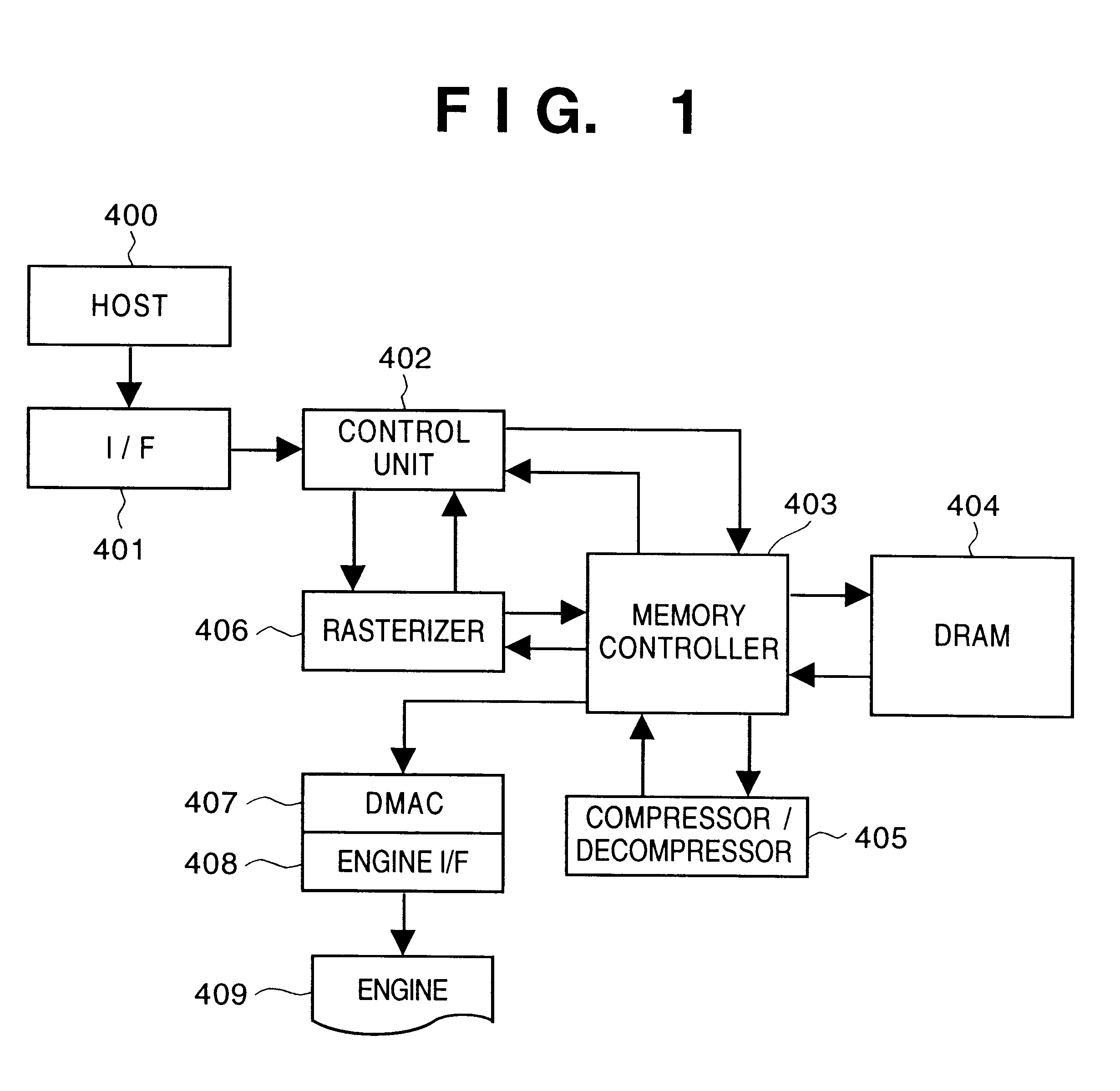
FIG. 1 is a block diagram showing the general structure of a printer controller according to a first embodiment of the present invention. The components in the printer controller will now be described.

An interface 401 receives print data from a source 400 for supply of data such as the host computer and performs an exchange of status with the host. More specifically, the interface 401 is a parallel interface, serial interface or network interface, etc.

A control unit 402 controls the overall printer apparatus and executes data processing. More specifically, the control unit 402 uses a processor such as a CPU to control the analysis of print data, the generation of image data and the various component with which the apparatus is provided.

A memory controller 403 controls a DRAM 404, which is a main memory provided within the printer controller. The memory controller 403 controls data access from a rasterizer 406 to a compression / decompression unit 405 and DMAC 407, refreshes the DRAM 4...

second embodiment

The first embodiment has been described in regard to a case where pre-rendering is designated by the data supply source on a per-band basis. Such an arrangement makes it possible to obtain some degree of improvement in total performance inclusive of the performance of the data supply source. In accordance with the second embodiment, the host computer designates a pre-rendering processing method of the kind shown in FIGS. 5A.about.5C as well as a conventional intermediate code processing method for the objects in one band. More outstanding effects can be obtained if the printing apparatus executes processing, in the manner described below, in regard to two types of data for which different processing methods have been designated.

FIGS. 8A and 8B are diagrams showing examples of images in which character data for which intermediate code processing has been designated and image data for which compression / decompression processing has been designated are mixed in one and the same band. Ar...

third embodiment

In accordance with the third embodiment, the manner in which objects overlap in a portion where such overlap occurs is stored in memory. Without changing a pre-rendering processing designation or intermediate code processing designation in regard to the objects, each object is processed just as designated.

First, the printer receives code data specific to the printer or draw data described in PDL or the like from the data supply source such as the host computer 400 and the controller 402 stores the received data in the DRAM 404 via the memory controller 403 (step S1201). In order to compensate for a difference in speed between the communication speed of the interface and the data processing speed, the received data generally is buffered temporarily in the reception buffer provided in the DRAM 404. The processing of step S901 corresponds to this operation.

Next, the control unit 402 analyzes the buffered input data and converts the data to internal data suited to band processing. At th...


PUM


Abstract

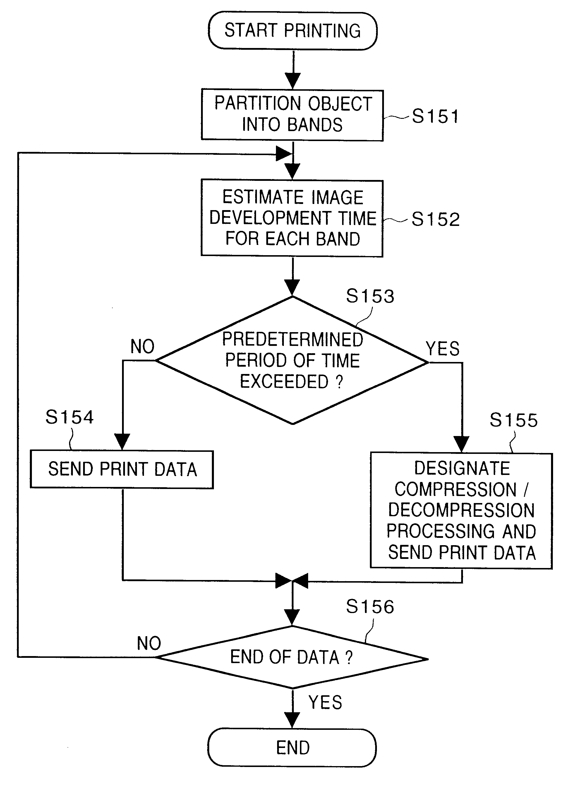
When a host computer transmits print data to a printer, the computer investigates the possibility of overrun per each band of band obtained by partitioning a page into bands. The host computer designates pre-rendering processing in regard to bands in which overrun is judged to be possible. Upon receiving the print data, the printer generates and compresses image data beforehand in regard to a band for which pre-rendering has been designated and stores the compressed image data. In case of a band for which pre-rendering has not been designated, the printer generates an intermediate code at a stage prior to the generation of image data from the print data. At the time of printing, image data is generated in one of two band buffers and image data is output from one band buffer. At this time the compressed image data is decompressed in case of a band for which pre-rendering has been designated, and image data is generated from an intermediate code in case of a band for which an intermediate code has been generated.

Description

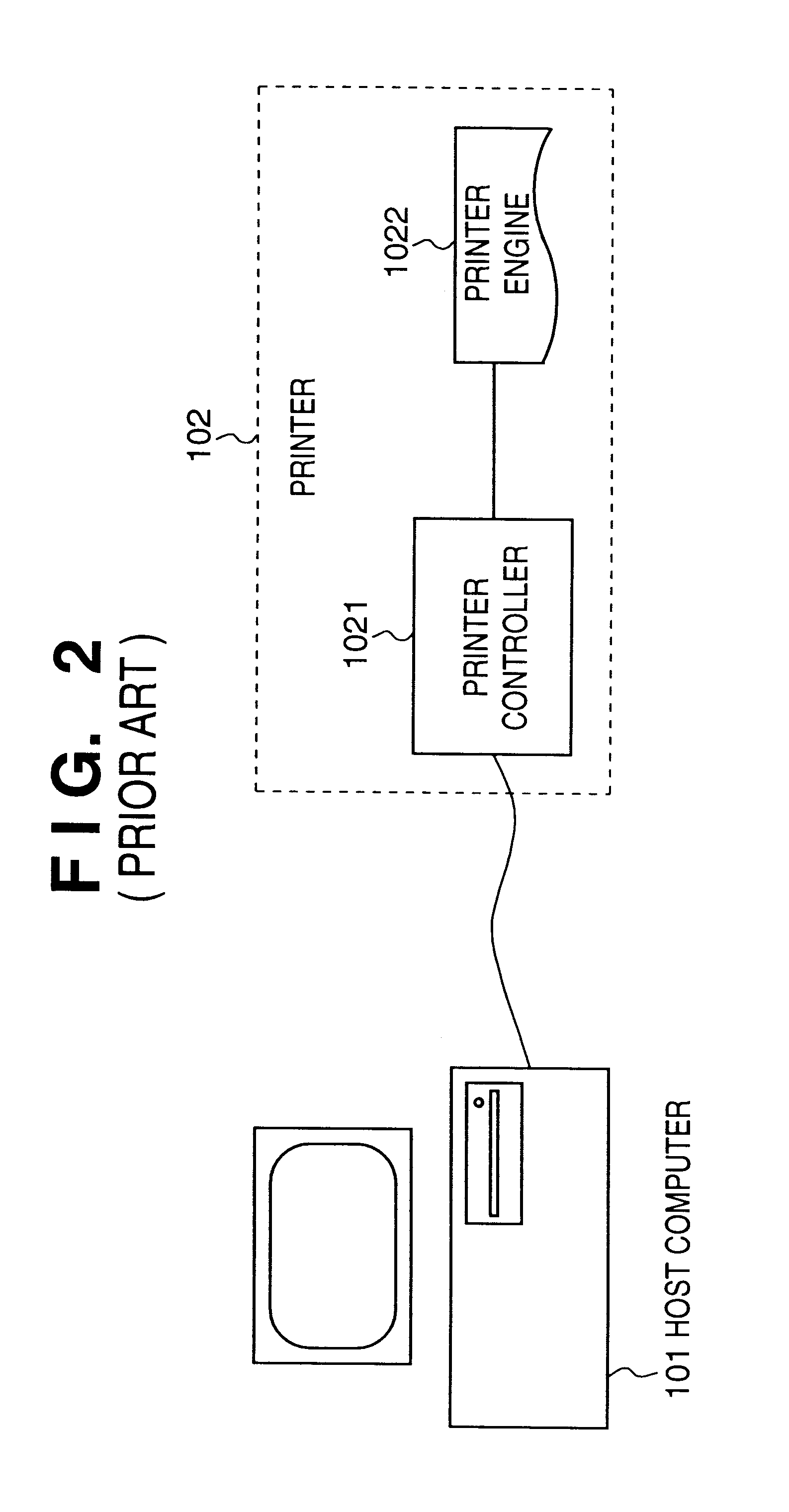
1. Field of the InventionThis invention relates to an image output control method and printing apparatus for receiving print data from a source for supply of data such as a host computer and printing out the data on a medium such as paper.2. Description of the Related ArtA system for processing and printing documents such as a document creating and printing system generally is constructed as shown in FIG. 2. The system is constituted by a host computer 101 serving as a processor for subjecting an output document to processing such as typesetting, and a printer 102 connected to the host computer 101 for fixing output document data, which is the result of processing by the host computer, on a medium such as paper by performing printing on the medium. More specifically, the user employs the host computer 101 to edit an image that is to be output. When editing ends, the host computer 101 converts the edited document data to an output image, i.e. print data, that will be accepted by the ...

Claims


Application Information

Patent Timeline
IPC IPC(8): G06K15/12B41J5/30G06F3/12
CPCG06K15/12G06K15/1865G06K15/1861G06K15/1823
Inventor IKEDA, JUN
Owner CANON KK
Learn More