Passive optical network arrangement

a technology of optical network and optical elements, applied in multiplex communication, instruments, optical elements, etc., can solve the problems of excessive cost, excessive duct congestion, and high cost, and achieve high loss path, high loss path, and high loss path

Inactive Publication Date: 2002-02-26
CIENA
View PDF6 Cites 107 Cited by
  • Summary
  • Abstract
  • Description
  • Claims
  • Application Information

AI Technical Summary

Benefits of technology

In a further preferred embodiment, a relatively high loss path is provided between one of said through ports and each of said drop ports.
According to a further aspect of the present invention there is provided a method of providing a PON comprising: providing a pair of transceivers, providing a plurality of optical fibre lengths; providing at least one splitter / combiner drop point arrangement; connecting said fibre lengths and said splitter / combiner drop point arrangement to form a linear network connecting said at least one splitter / combiner drop point arrangement and connecting said transceivers to opposite ends of said linear network; and wherein one transmitter and one receiver of said pair of transceivers operates in main mode and another transmitter and another receiver of said pair of transceivers operates in warm standby mode; and arranged to provide single point failure protection in the network between said transceivers.

Problems solved by technology

This doubles the fibre feeder requirements, with consequent potential duct congestion and excessive costs, and is especially expensive for long thin routes where duct space is also generally scarce.
SDH / SONET rings are good for supporting larger businesses, but become expensive when only a few E1 / T1's are required, especially if the locations of the subscribers' drop points are scattered.
This has so far not happened since PON systems could not provide the high levels of availability required at competitive prices.

Method used


Image

  • Passive optical network arrangement
  • Passive optical network arrangement
  • Passive optical network arrangement

Examples


Embodiment Construction

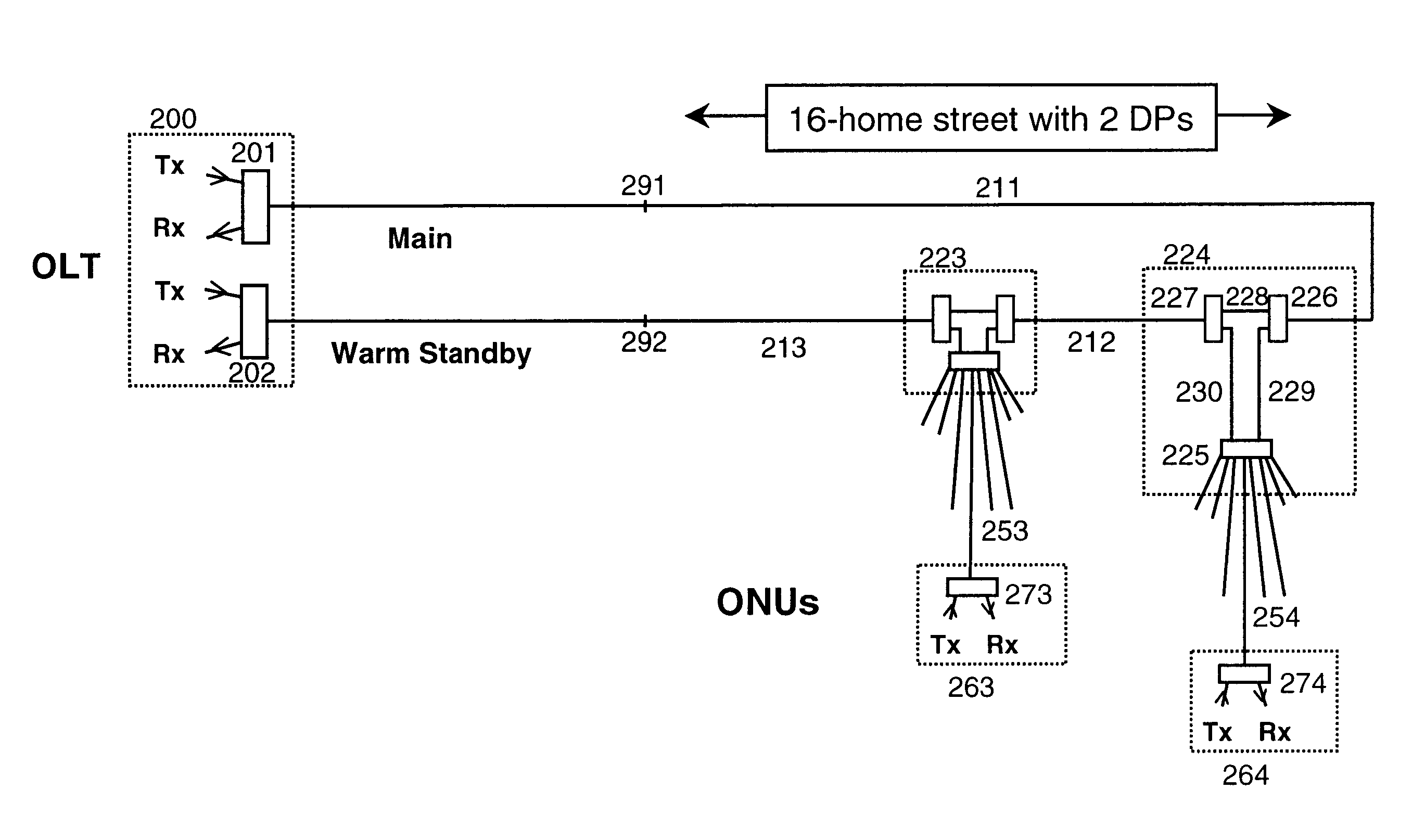
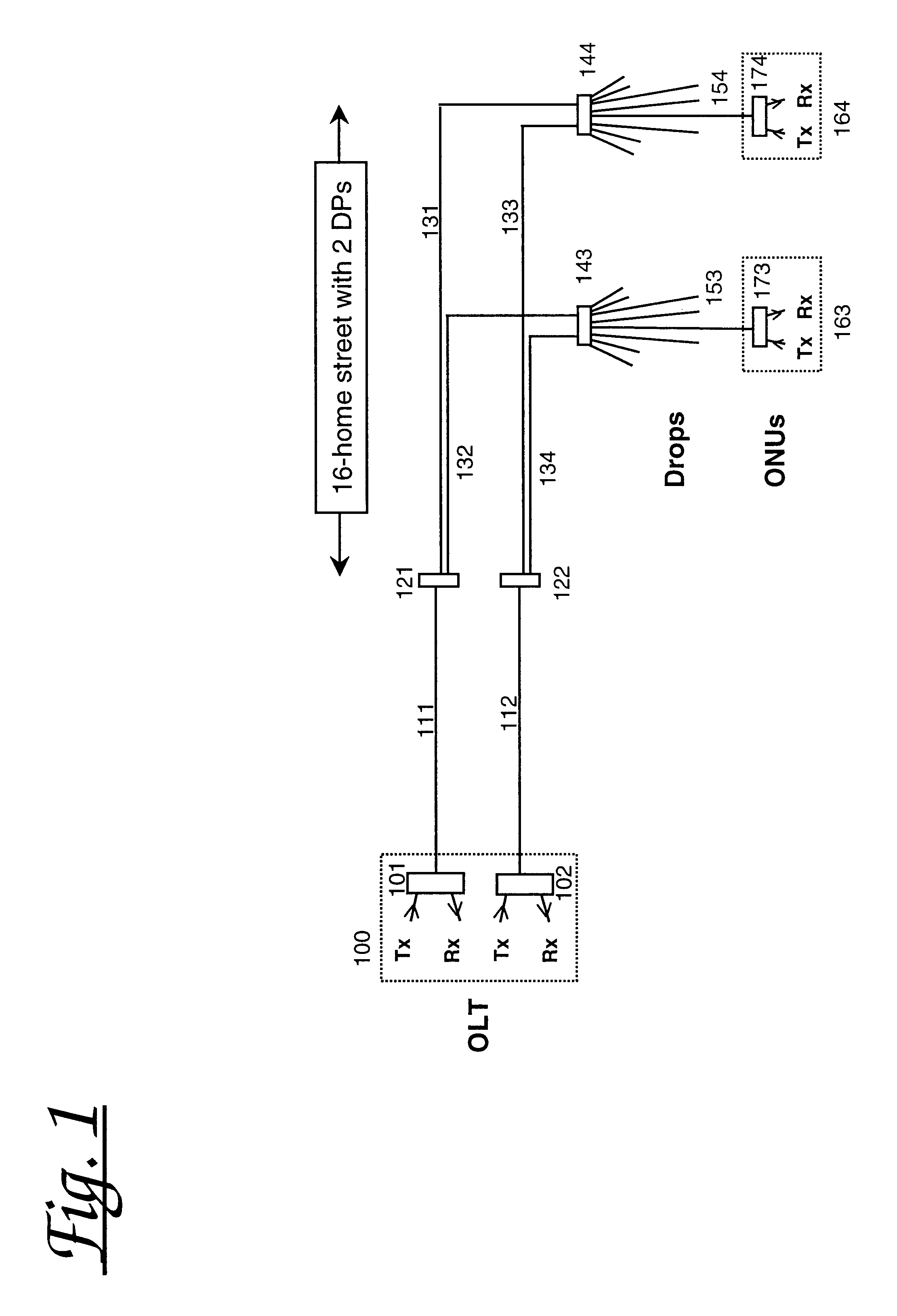
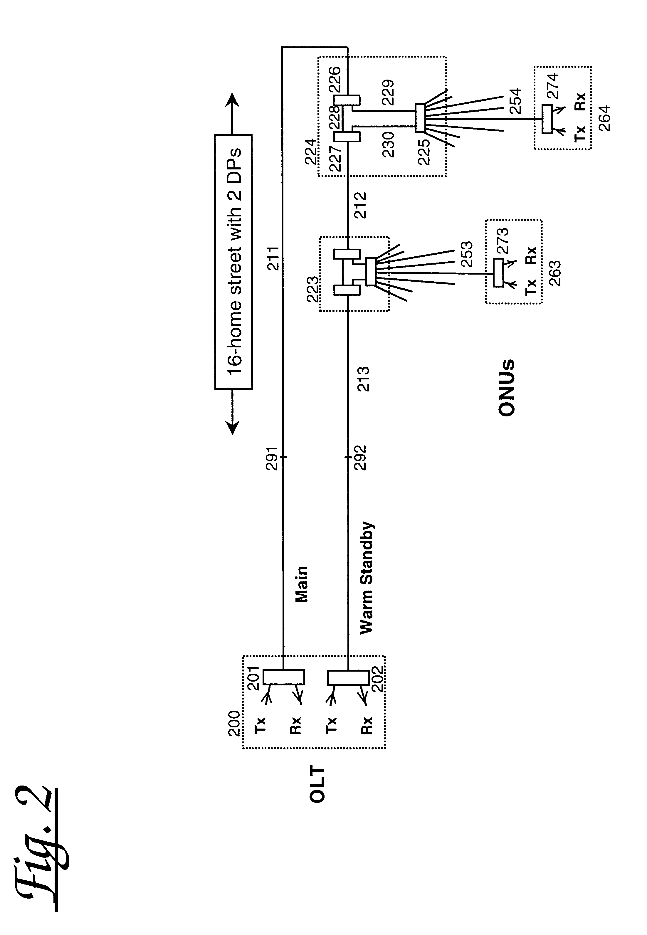
FIG. 1 shows, for comparison purposes, a protected PON according to the prior art arranged for distributing signals between an Optical Line Terminal (OLT) 100 and multiple Optical Network Units (ONU's) 163, 164. Specifically the arrangement comprises an OLT 100 comprising first and second optical transceivers 101, 102 connected via fibre feeder lines 111, 112 to initial distribution splitter / combiners 121, 122 respectively. Each of the initial distribution splitter / combiner is connected by means of fibre distribution lines 131-134 to each of two drop points each comprising an optical splitter / combiner 143, 144 respectively. The drop point splitter / combiners 143, 144 are each connected via final drop distribution lines 153, 154 to subscriber ONUs (of which two are illustrated 163, 164). Each optical splitter / combiner is shown with eight associated final drop distribution lines, though only one ONU is shown per optical splitter.

For the arrangement shown, losses in each of the initial ...


PUM


Abstract

A passive optical network having a plurality of optical splitters / combiners each comprising first and second through ports and at least one drop port. The through ports of the plurality of splitters / combiners are concatenated to form a linear arrangement having two end through ports. Optical signals may be transmitted between the end through ports by means of the linear arrangement; and signals may be transmitted between at least one of the end through ports and one of the drop ports by means of the linear arrangement. The splitter / combiners can be inserted to form drop points in a ring or dual-homed passive optical network to provide flexibility in provision of protection and network reconfiguration.

Description

The present invention relates to passive optical networks, and in particular to a method and apparatus for providing flexibility in the protection afforded by such networks.BACKGROUND TO THE INVENTIONPassive optical networks (PON) are known to be effective for distributing broadband and cable TV services directly to customers using optical fibre. Current passive optical network systems can offer full protection down to the customer but require complete duplication of (a) the fibre feeder from the exchange, (b) the splitter / combiners, (c) the customer drops, and (d) the electro-optical transceivers.PON feeder protection alone requires duplication of every fibre down to every drop splitter. This doubles the fibre feeder requirements, with consequent potential duct congestion and excessive costs, and is especially expensive for long thin routes where duct space is also generally scarce.There is at present therefore a strong demand from network operators to reduce the costs of fibre dep...

Claims


Application Information

Patent Timeline
Patent Type & Authority Patents(United States)
IPC IPC(8): H04B10/207H04B10/213H04J3/16H04B10/272H04Q11/00
CPCH04B10/272H04Q2011/0081H04Q11/0067
Inventor DYKE, PETER JOHNDYER, MICHAEL PHILIP
Owner CIENA
Why Eureka
Try Eureka