Monitoring device and system

a technology applied in the field of monitoring device and system, can solve problems such as inability to d

Inactive Publication Date: 2007-09-27
FUJITSU LTD
View PDF8 Cites 2 Cited by
  • Summary
  • Abstract
  • Description
  • Claims
  • Application Information

AI Technical Summary

Benefits of technology

[0024]It is accordingly an object of the present invention to provide a monitoring device (or method) and system which can detect a failure point of a processor within a device such as a FPGA, a LSI, or a memory and a failure point of a transmission line connected to the processor.

Problems solved by technology

However, there has been a problem that it is not possible to detect which of the transmission lines has caused the failure.
Although, in a device such as the FPGA, the LSI, or the memory, for example, a failure that a program logic of an internal processor is rewritten due to neutrons or the like in the atmosphere, or a failure that the internal processor malfunctions due to a bit garble by noise or the like may occur, the above-mentioned patent document 1 can not detect such a failure point in the processor within the device.

Method used


Image

  • Monitoring device and system
  • Monitoring device and system
  • Monitoring device and system

Examples


Embodiment Construction

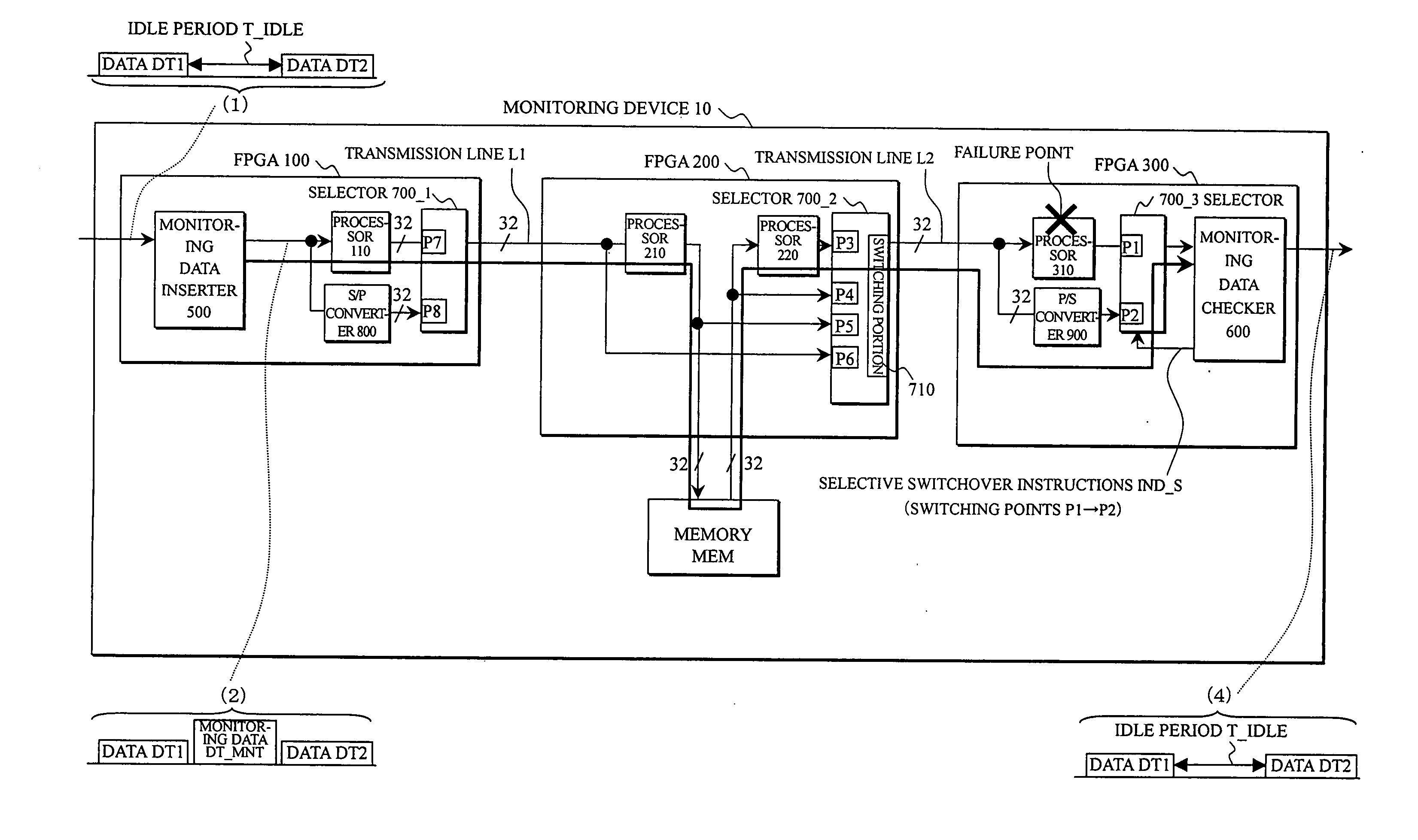
[0087]Embodiments [1]-[3] of the monitoring device and an Embodiment [4] of the monitoring system according to the present invention is shown in principle in FIG. 1 will now be described referring to FIGS. 2, 3, 4A, 4B, 4C, 5A, 5B, 6-11, 12A, 12B, and 13-17.

⊚Embodiment [1]: FIGS. 2, 3, 4A-4C, 5A, 5B, 6-11, 12A, 12B, 13, and 14

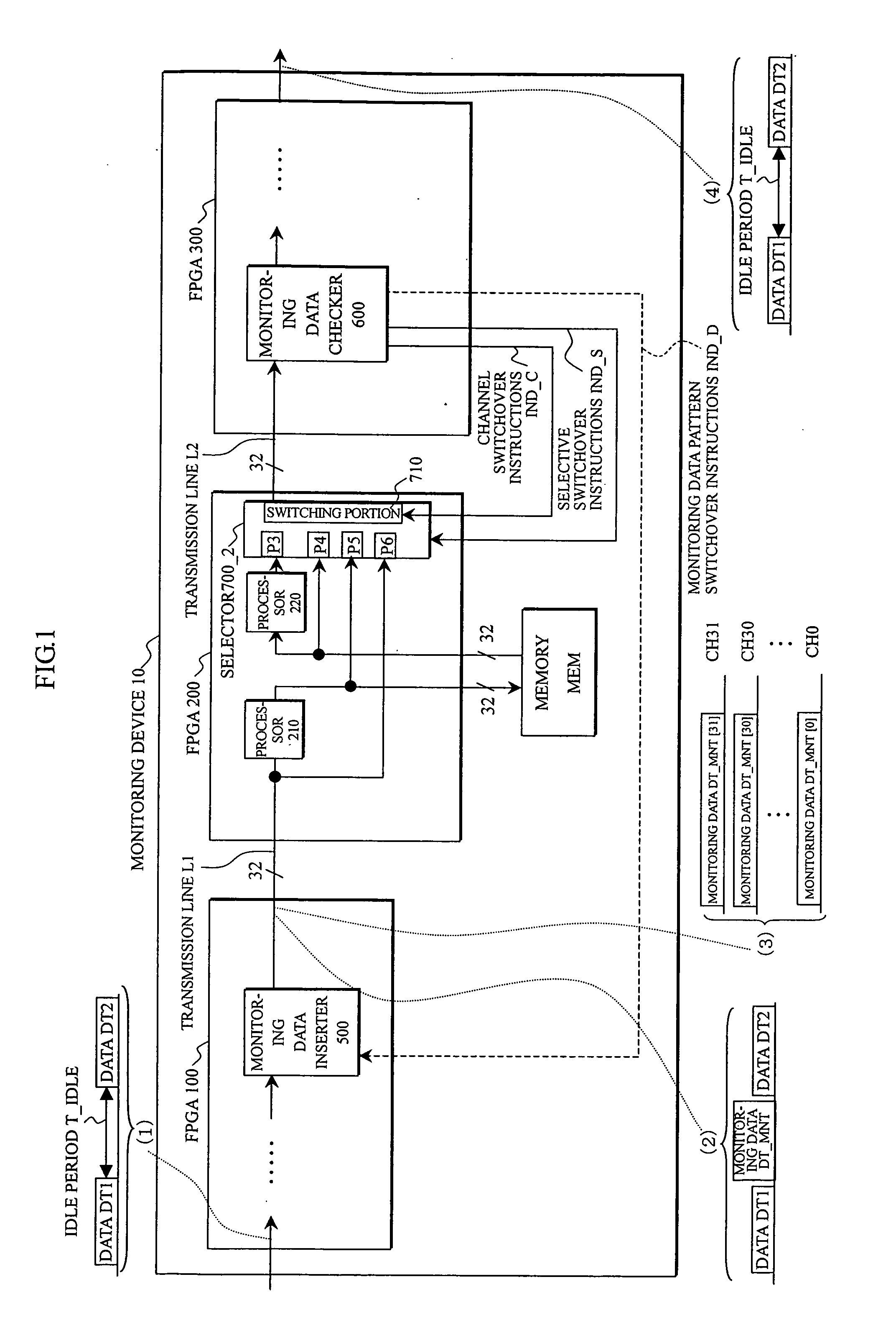
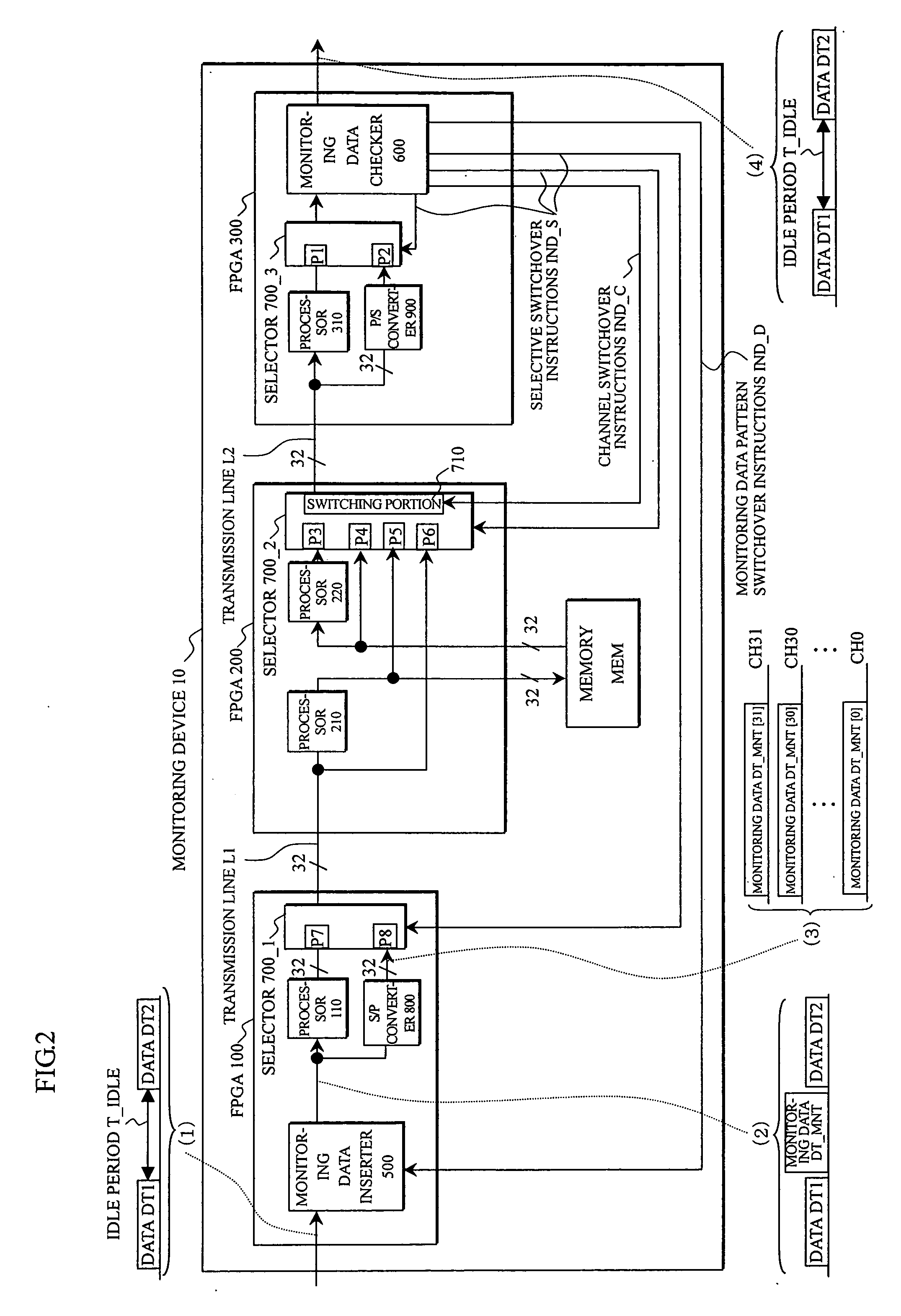
[1]-1 Arrangement: FIG. 2

[0088]The monitoring device 10 shown in FIG. 2 includes, in the same way as FIG. 1, the FPGA 100 provided with the monitoring data inserter 500, the FPGA 200 provided with the processors 210 and 220, the selector 700_2, and the switching portion 710, the FPGA 300 provided with the monitoring data checker 600, and the memory MEM. Also, the FPGA 100 and the FPGA 200, as well as the FPGA 200 and FPGA 300 are respectively connected with the transmission lines L1 and L2 which are respectively composed of e.g. 32 channels.

[0089]Furthermore, the FPGA 100 and the FPGA 300 are respectively provided with, in addition to the arrangement shown in F...


PUM


Abstract

In a monitoring device and system, a monitoring data inserter inserts monitoring data of a predetermined pattern into an idle period of input data to be transmitted to a transmission line. A monitoring data checker having received the monitoring data through the transmission line, when determining that the monitoring data does not maintain the predetermined pattern, provides selective switchover instructions to a selector to be controlled. Then, the monitoring data checker sequentially performs a selective switchover to processors, thereby detecting a failure point in the processors. Also, when the failure point in the processors can not be detected, the monitoring data checker provides channel switchover instructions to a switching portion and performs a channel switchover of the transmission line, thereby detecting which channel of the transmission line has caused a failure.

Description

BACKGROUND OF THE INVENTION[0001]1. Field of the Invention[0002]The present invention relates to a monitoring device and system, and in particular to a monitoring device (or method) and system for detecting a failure in a rewritable device such as an FPGA (Field Programmable Gate Array), an LSI (Large Scale Integration), or a memory mounted on a frame converting device or the like.[0003]2. Description of the Related Art[0004]A frame switching system shown in FIG. 18 is composed of an Ethernet (registered trademark) network 1, frame converting devices 2_1-2—n (hereinafter, occasionally represented by a reference numeral 2) for performing a conversion of an Ethernet frame into a SONET (Synchronous Optical Network) / SDH (Synchronous Digital Hierarchy) frame or a conversion of the SONET / SDH frame into the Ethernet frame, a switching equipment 3 for switching the frame according to destination information within the Ethernet frame or the SONET / SDH frame, and a telephone network 4 using SO...

Claims


Application Information

Patent Timeline
Patent Type & Authority Applications(United States)
IPC IPC(8): H04J1/16H04L69/40
CPCH04J3/14
Inventor YASUI, TAKANORISHIONO, HIDEKIHIROMORI, MASAKIFUJIYAMA, HIROFUMITOMIE, SATOSHI
Owner FUJITSU LTD
Why Eureka
Try Eureka