
Electronic circuits with directly integrated electrochemical cells

Active Publication Date: 2020-11-19
IMPRINT ENERGY
View PDF1 Cites 5 Cited by
  • Summary
  • Abstract
  • Description
  • Claims
  • Application Information

AI Technical Summary

Benefits of technology

The patent text describes a method for integrating electrochemical cells with other devices during cell manufacturing, resulting in cost and size reduction, improved mechanical and electrical integration, and fewer failure points. The integration occurs by sharing components, reducing operation steps, and eliminating additional failure points. The text also mentions that printing components of electrochemical cells allows for higher levels of mechanical and electrical integration.

Problems solved by technology

Specifically, the footprint of an electrochemical cell may be rather significant in comparison to other components, such as microprocessors, antenna, etc.
However, these conventional connection methods are not always applicable to thin flexible electrochemical cells, which utilize plastic substrates and / or plastic packaging components.
Not only the plastic substrate tend to interfere with the connection methods, but these plastic substrates are also not capable of withstanding high temperatures needed for conventional methods of connections.
Furthermore, plastic substrates tend to limit the amount of force that can be applied to external tabs while forming these connections.
However, this approach is very limited and not available for many other materials, such as aluminum, copper, carbon coated metals, or metals with protective coatings.
Likewise, laser welding is limited to particular materials, thicknesses and configurations and generally not applicable to parts with any coatings.
Laser welding is also prone to generating a lot of heat, which can damage surrounding parts or a substrate.
Exposure to such high temperatures is damaging to electrochemical cells, such as battery packaging, active materials, electrolyte, and the like.
These thin films can shrink and crease during heat exposure compromising the sealing of electrochemical cell.
In some examples, the packaging layer also comprises an adhesive (e.g., a rubber adhesive, an acrylic pressure sensitive adhesive), which is susceptible to high temperature exposure.
It should be noted that any coating on metal surfaces (e.g., carbon) tend to interfere with conventional connection methods.
As noted above and seen in FIGS. 5A and 5B, one challenge of forming electrical connections to cell terminals is proximity (e.g., direct interface) of these cell terminals to packaging layers, which are electrical insulators with limited heat stability.

Method used


Image

  • Electronic circuits with directly integrated electrochemical cells
  • Electronic circuits with directly integrated electrochemical cells
  • Electronic circuits with directly integrated electrochemical cells

Examples


Embodiment Construction

[0032]In the following description, numerous specific details are set forth in order to provide a thorough understanding of the presented concepts. The presented concepts may be practiced without some or all of these specific details. In other instances, well known process operations have not been described in detail so as to not unnecessarily obscure the described concepts. While some concepts will be described in conjunction with the specific examples, it will be understood that these examples are not intended to be limiting. On the contrary, it is intended to cover alternatives, modifications, and equivalents as may be included within the spirit and scope of the present disclosure as defined by the appended claims.

[0033]Various examples are described herein in the context of printable electrochemical cells, such as cells comprising multi-valent metal ions (e.g., Zn2+) for carrying the charge between the positive and negative electrodes. “Multivalent” is defined, for purposes of t...


PUM


Abstract

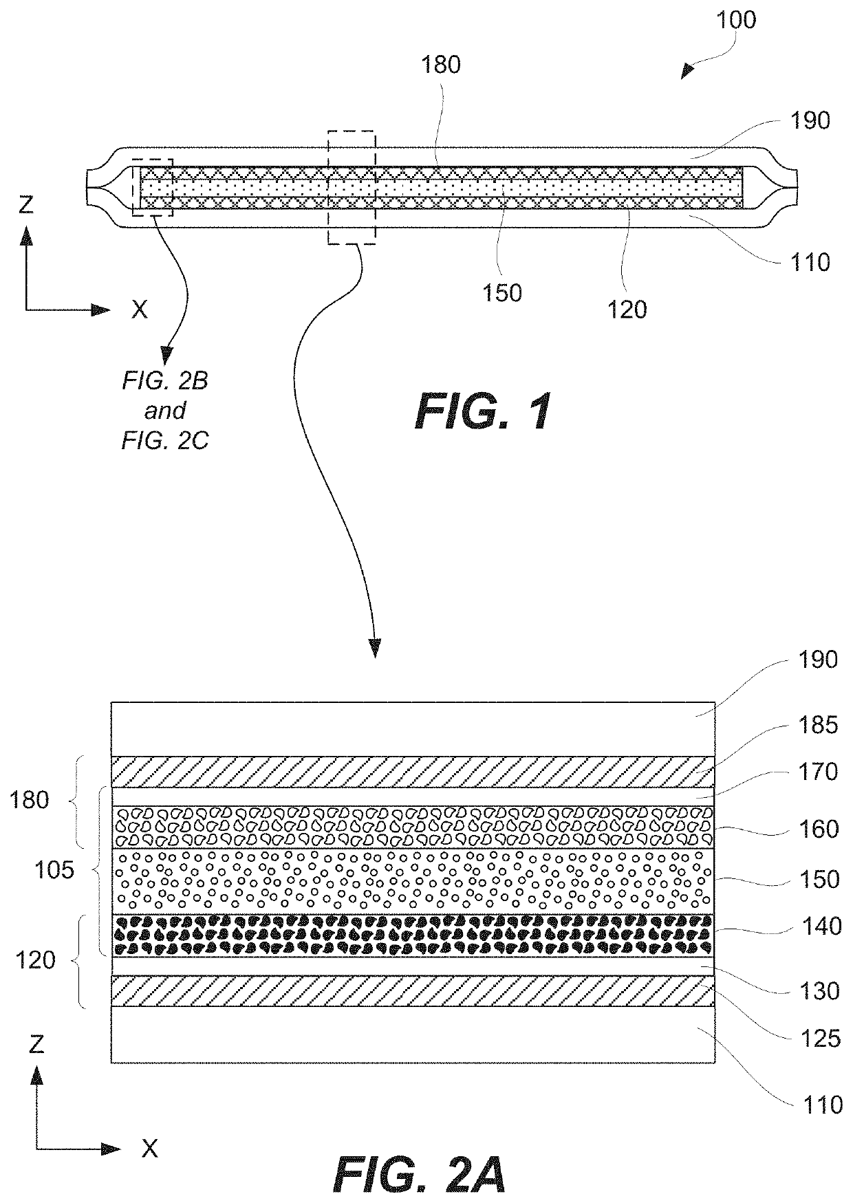
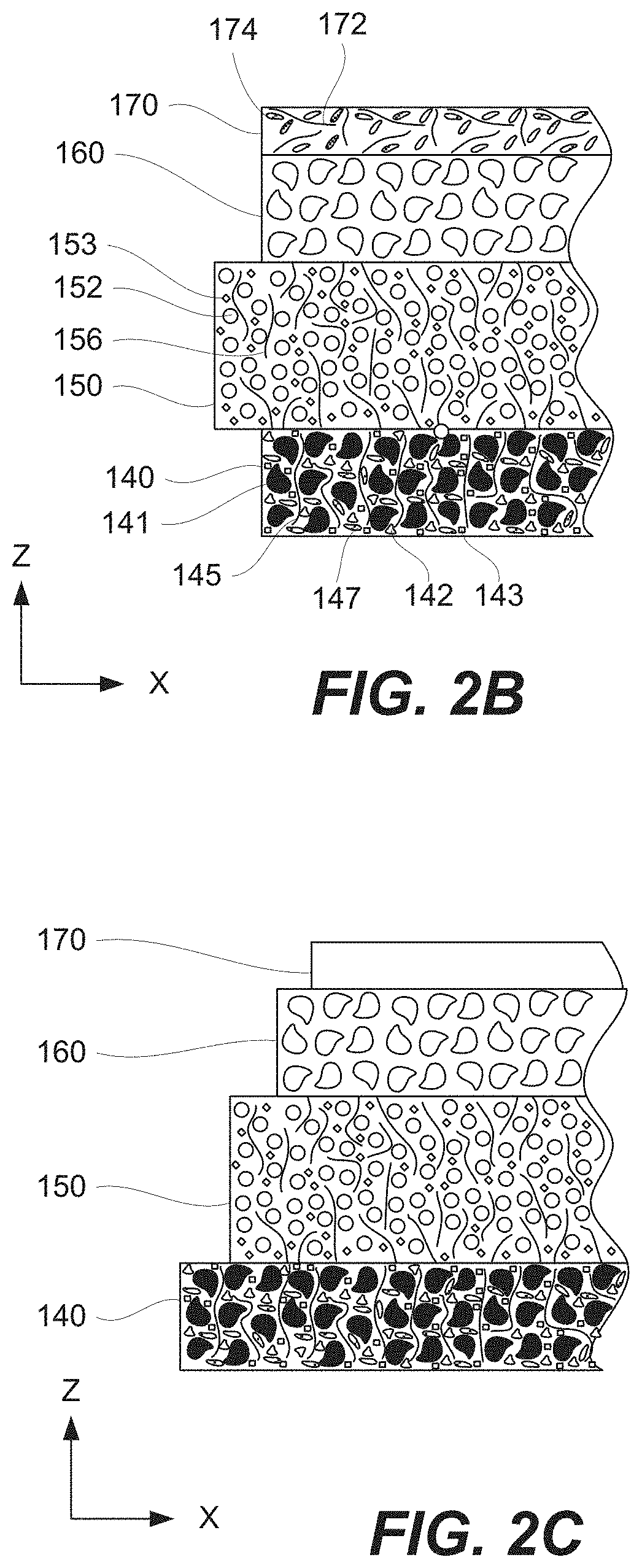
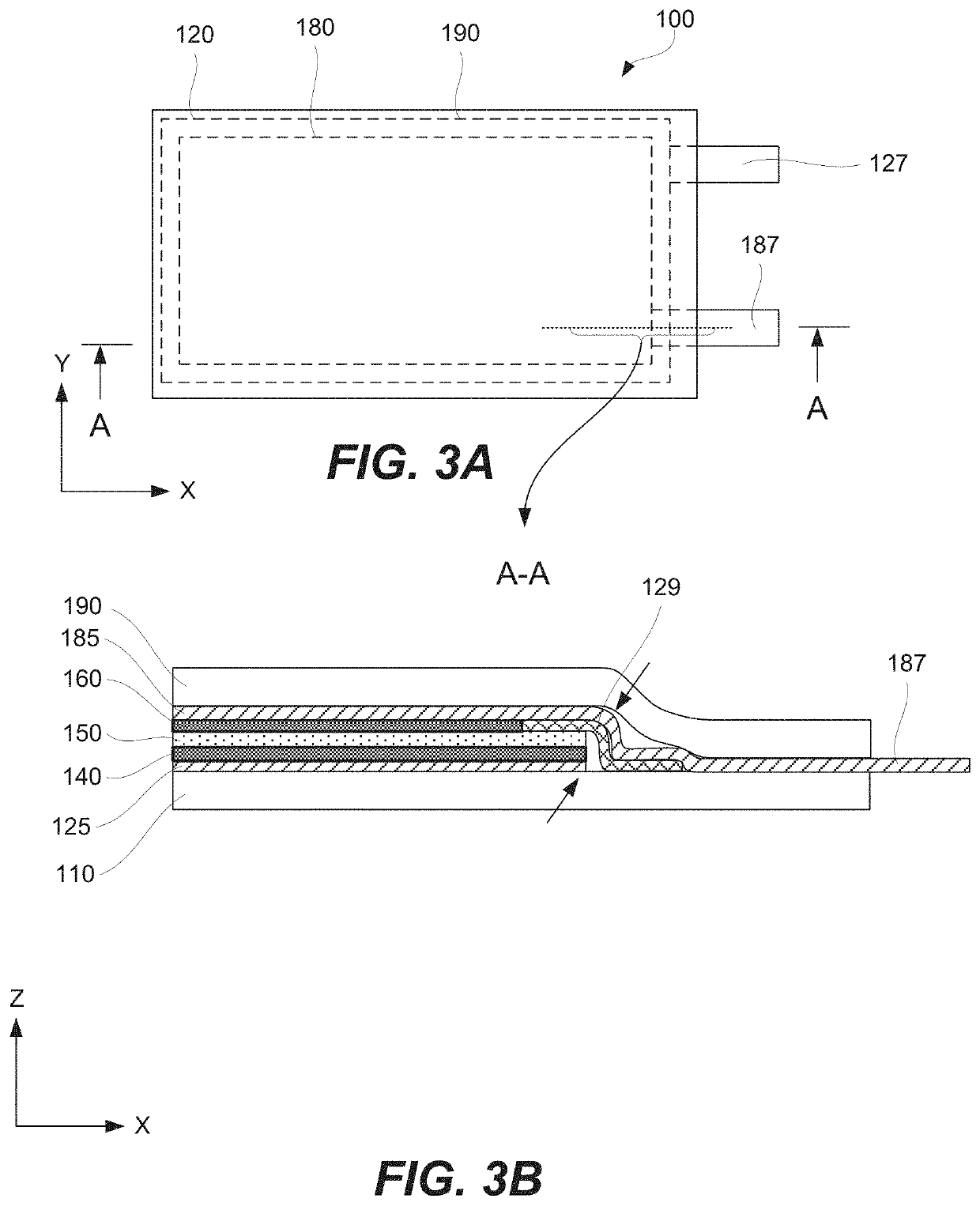
Provided are electronic circuits, comprising electrochemical cells directly integrated with other devices of the circuits, and methods of manufacturing these circuits. The direct integration occurs during cell manufacturing, which allows sharing components, reducing operation steps and failure points, and reducing cost and size of the circuits. For example, a portion of a cell enclosure may be formed by a circuit board, providing direct mechanical integration. More specifically, the cell is fabricated right on the circuit board. In the same or other examples, one or both cell current collectors extend outside of the cell boundary and used by other devices, providing direct electrical integration without a need for intermediate connections and eliminating additional failure points. Furthermore, printing one or more components of electrochemical cells, such as electrolytes and current collectors, allows achieving higher levels of mechanical and electrical integration that are generally not available in conventional cells.

Description

CROSS-REFERENCE TO RELATED APPLICATIONS[0001]This application claims the benefit under 35 U.S.C. § 119(e) of U.S. Provisional Patent Application 62 / 849,257, entitled: “ELECTRONIC CIRCUITS WITH DIRECTLY INTEGRATED ELECTROCHEMICAL CELLS”, filed on 2019 May 17, which is incorporated herein by reference in its entirety for all purposes.BACKGROUND[0002]Various design aspects and techniques used for manufacturing of conventional electrochemical cells typically preclude direct integration of these electrochemical cells into circuits, powered by these electrochemical cells, as well as other components. Instead, this integration occurs in a separate process, i.e., after the electrochemical cells are fully manufactured. This conventional integration, which may also be referred to as a multi-stage integration, requires additional operations, components, and costs in comparison to the direct integration. For purposes of this disclosure, the direct integration is defined as a process of integrat...

Claims


Application Information

Patent Timeline
IPC IPC(8): H01M4/04H01M10/42H01M10/04
CPCH01M10/04H01M4/0402H01M10/425Y02E60/10H01M10/4257H01M4/0414H01M50/536H01M50/105Y02P70/50
Inventor SMITHYMAN, JESSETIKHONOV, KONSTANTINHO, CHRISTINEGURR, ALEXANDER
Owner IMPRINT ENERGY
Learn More