Engineered polymeric valves, tubular structures, and sheets and uses thereof

a technology tubular structures, applied in the field of engineered polymeric valves, tubular structures, sheets, etc., can solve the problems of lack of long-term durability of mechanical valves, affecting the quality of mechanical valves, and generating clicking noise of mechanical valves, etc., to achieve the effect of eliminating failure at high-stress points

Inactive Publication Date: 2021-07-08
PRESIDENT & FELLOWS OF HARVARD COLLEGE
View PDF0 Cites 1 Cited by
  • Summary
  • Abstract
  • Description
  • Claims
  • Application Information

AI Technical Summary

Benefits of technology

[0009]The present invention is based, at least in part, on the discovery of methods for the assembly of engineered tubular structures, such as valves, comprising oriented polymeric fibers, e.g., nanofibers. The methods of the present invention are simpler than previous methods and permit the fabrication of tubular structures, such as replacement valves, without the use of sutures to attach valve leaflets to a valve conduit. In addition, the methods of the present invention permit the fabrication of valves without the use of melt processing, thereby substantially eliminating failure at high-stress points.

Problems solved by technology

However, mechanical valves suffer from the disadvantage that they are thrombogenic and, thus, the patient requires lifetime anticoagulant therapy which is expensive and potentially dangerous in that it may cause abnormal bleeding which, in itself, can cause a stroke if the bleeding occurs within the brain.
In addition, mechanical valves also generate a clicking noise when the mechanical closure seats against the associated valve structure at each beat of the heart.
The major disadvantage of bioprosthetic valves is that they lack the long-term durability of mechanical valves.
In addition, naturally occurring processes within the human body can attack and stiffen or “calcify” the tissue leaflets of the bioprosthetic valve over time, particularly at high-stress areas of the valve, such as at the commissure junctions between the valve leaflets and at the peripheral leaflet attachment points or “cusps” at the outer edge of each leaflet.
Further, bioprosthetic valves are subject to stresses from constant mechanical operation within the body.
Although these tissue-engineered valves can overcome the need for anticoagulants as well as the need for open heart surgery, their very composition sacrifices durability.
On average, these heart valves are only expected to last 15 years in the patient before the over 600 million open-close cycles within this time frame cause significant fatigue that warrants replacement.
Although this lifecycle of these tissue-engineered valves may be less relevant for the aging patient population that requires replacement semilunar valves as a result of atherosclerosis or calcification, it is a significant problem for children born with congenital valve defects.
Because these current animal sourced valves are non-regenerative and eventually fatigue, children needing valve repair or replacement will have to undergo numerous surgeries throughout their lifetime.
Although many of these studies have shown promising results of tissue remodeling and integration into the body, there still remains a significant gap between research usage and commercial adoption of this type of tissue engineered valve.
Unfortunately, these materials are still far from ideal.
They are expensive, potentially immunogenic and further they show toxic degradation and inflammatory reactions.
In addition, they are of poor resorbability.
As a consequence, there is a lack of growth and risk of thromboembolic complications, degeneration and infections.
Furthermore, tissue engineering of highly customized valve scaffolds doped with growth factors or seeded with stem cells and cultured in the lab prior to implantation results in a very costly and specialized valve implant.
These valves, although mechanically sound and biocompatible require several fabrication steps.
As such, there may be an increased risk of valve failure at the connection points and / or lack of tissue remodeling as native cells fail to repopulate properly at the connection points.
Furthermore, to deliver these valves via a minimally invasive procedure, pieces of the valve (e.g., valve leaflets) may need to be cut and sutured onto a stent by a skilled surgeon, which increases the complexity and time required for the procedure.

Method used


Image

  • Engineered polymeric valves, tubular structures, and sheets and uses thereof
  • Engineered polymeric valves, tubular structures, and sheets and uses thereof
  • Engineered polymeric valves, tubular structures, and sheets and uses thereof

Examples


Embodiment Construction

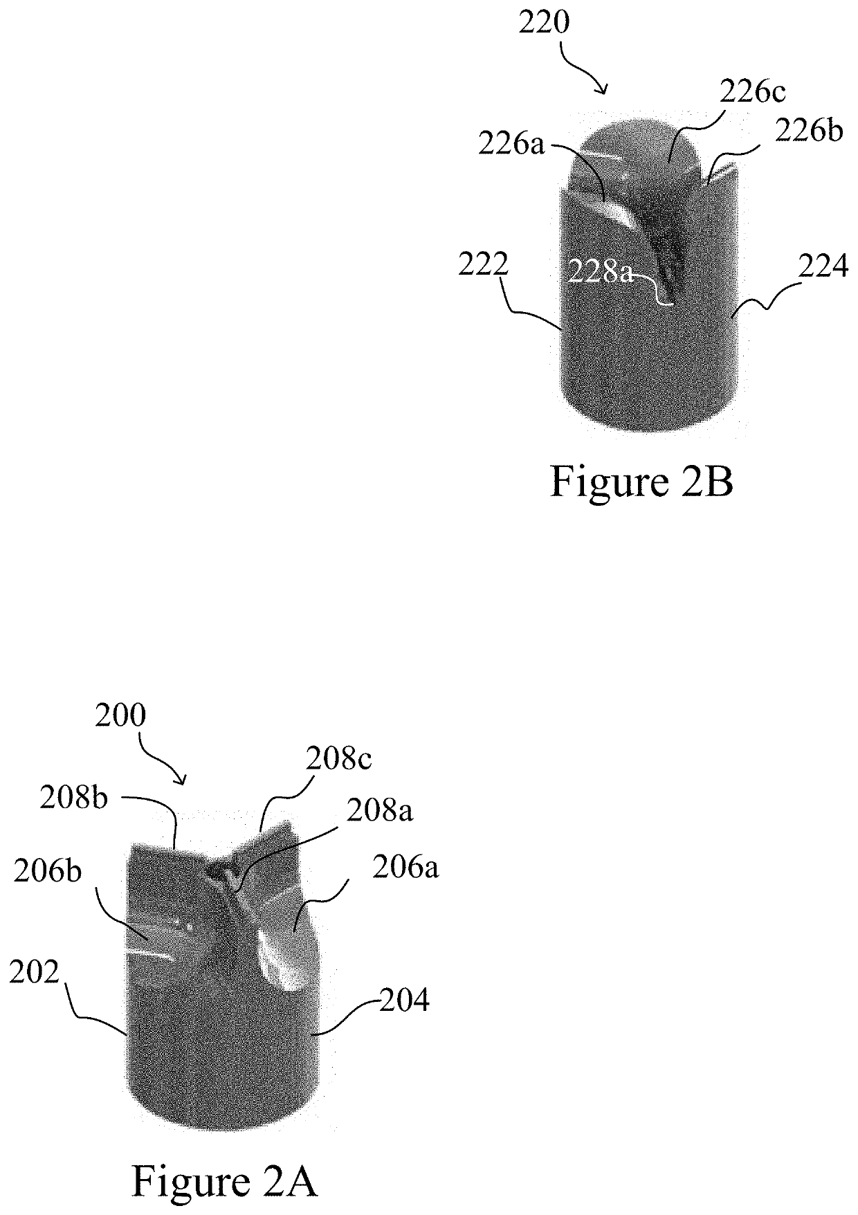
[0057]The present invention is based, at least in part, on the production and assembly of engineered tubular structures including oriented polymeric fibers that are suitable for use as, for example, engineered cardiac valves.

I. Methods for Generating Engineered Valve Structures

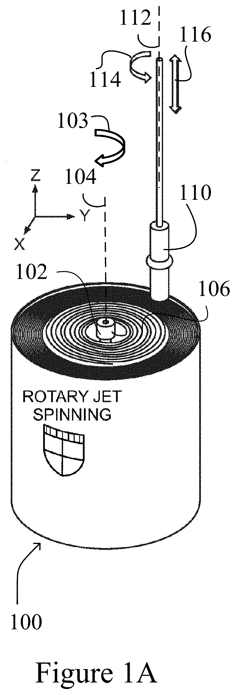
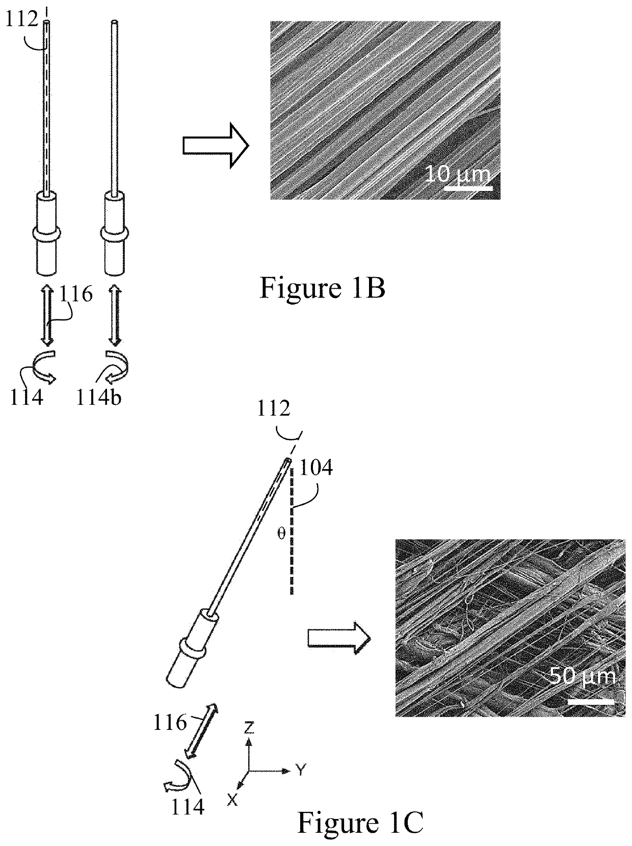
[0058]Methods for generating engineered valve structures of the invention may include a step of configuring micron, submicron or nanometer dimension polymeric fibers in a desired shape.

[0059]Suitable devices and use of the devices for fabricating the micron, submicron or nanometer dimension polymeric fibers for use in the methods of the present invention are described in U.S. Patent Publication No. 2012 / 0135448, U.S. Patent Publication No. 2013 / 0312638, and U.S. Patent Publication No. 2014 / 0322515, the contents of each of which are incorporated in their entirety by reference.

[0060]The micron, submicron or nanometer dimension polymeric fibers may have a diameter of about 15, 20, 25, 30, 35,40, 45, 50, 55, 60, 6...


PUM

PropertyMeasurementUnit
diameteraaaaaaaaaa
diameteraaaaaaaaaa
diameteraaaaaaaaaa

Abstract

The present invention provides engineered valves, tubular structures, and sheets comprising oriented polymeric fibers, e.g., nanofibers, methods of fabricating such structures, and methods of use of such structures as, for example, patches, grafts and valves, e.g., cardiac valves.

Description

RELATED APPLICATIONS[0001]This application is a continuation of U.S. patent application Ser. No. 15 / 112,528, filed on Jul. 19, 2016, which is a 35 U.S.C. § 371 national stage filing of International Application No. PCT / US2015 / 012646, filed Jan. 23, 2015, which in turn claims the benefit of priority to U.S. Provisional Patent Application No. 61 / 930,746, filed Jan. 23, 2014. The entire contents of each of the foregoing applications are incorporated herein by reference.GOVERNMENT SUPPORT[0002]This invention was made with government support as a subcontract issued under Prime Contract Number DE-AC52-06NA25396 between Los Alamos National Laboratory and the United States Department of Energy (DOE) and the National Nuclear Science Administration (NNSA). The government has certain rights in the invention.BACKGROUND OF THE INVENTION[0003]Over 150,000 surgical procedures are performed each year to replace damaged or diseased cardiac valves worldwide. For example, mechanical heart valve prosth...

Claims


Application Information

Patent Timeline
Patent Type & Authority Applications(United States)
IPC IPC(8): A61F2/24A61L27/50A61L27/14A61L27/18A61L27/26A61L27/38D01D5/18D01D7/00
CPCA61F2/2415A61F2/2412A61L27/50A61L27/507A61L27/14A61L2430/20A61L27/26A61L27/3839D01D5/18D01D7/00A61L2400/12A61L27/18
Inventor PARKER, KEVIN KITCAPULLI, ANDREW K.GOSS, JOSUE A.
Owner PRESIDENT & FELLOWS OF HARVARD COLLEGE
Why Eureka
Try Eureka