Immobilization system for watercraft

Inactive Publication Date: 2002-03-05
YAMAHA MOTOR CO LTD
View PDF11 Cites 90 Cited by
  • Summary
  • Abstract
  • Description
  • Claims
  • Application Information

AI Technical Summary

Benefits of technology

FIG. 11 is a flowchart illustrating a control subroutine in accordance with another aspect of the present in

Problems solved by technology

Unfortunately, this increase in popularity has also brought about an increase in personal watercraft theft.
The problem with using a lanyard switch as the only means of antitheft protection is that other plates and mechanisms can be substituted for the lock plate thus allowing the engine to start and operate without using the lock plate originally supplied with the watercraft.
As a result, the lanyard switch alone does not provide significant antitheft protection.
One drawback of this type of antitheft ignition key is that the

Method used


Image

  • Immobilization system for watercraft
  • Immobilization system for watercraft
  • Immobilization system for watercraft

Examples


Embodiment Construction

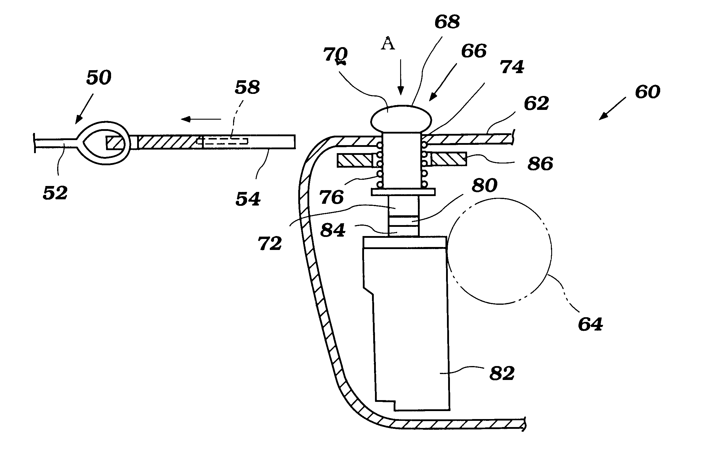
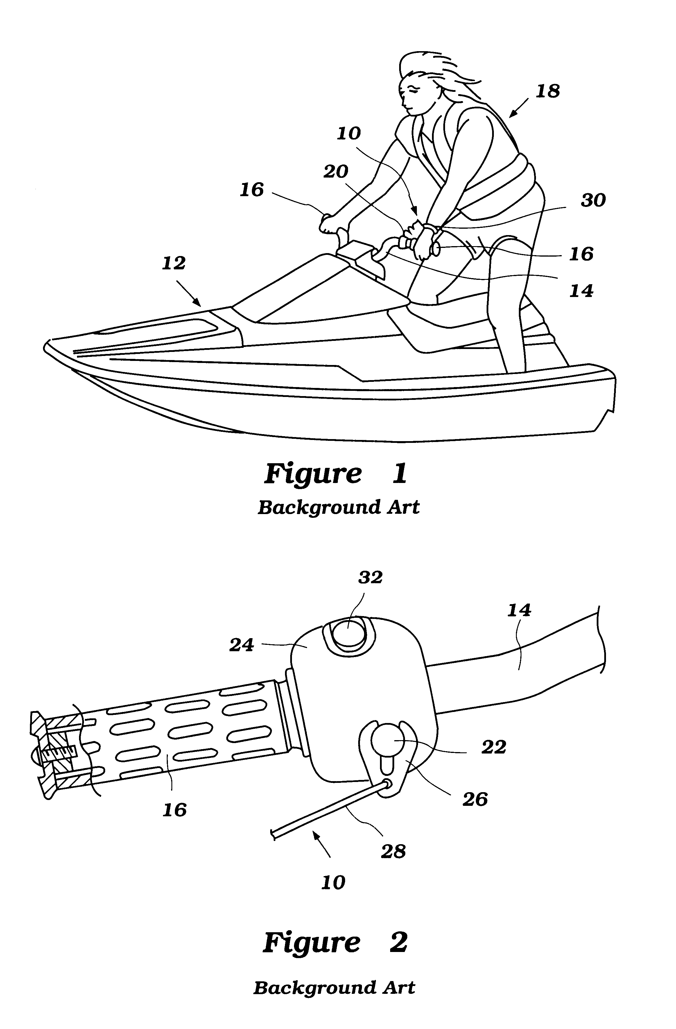
The present invention is directed to an immobilization system for a watercraft. In general, the immobilization system includes a lanyard assembly which functions as a kill switch for an engine of a watercraft when a user of the watercraft moves their arm sufficiently far from the engine controls to activate the lanyard. Those of skill in the art will appreciate that the invention has particular utility for a personal watercraft but can also be used or adapted for use in a variety of other settings, for example, without limitation, open hull boats and outboard motors.

With reference to FIGS. 5 and 6, a lanyard assembly 50 constructed in accordance with one aspect of the present invention is illustrated therein. The lanyard assembly 50 includes a tether 52 (shown partially) connected to a lanyard member 54.

The lanyard member 54 includes an aperture 56 through which the tether 52 passes so as to reliably attach the tether 52 to the lanyard member 54. The other end of the tether 52 (not ...


PUM


Abstract

An immobilization system for watercraft includes a transponder mounted within a lanyard clip and a communication device mounted to be in the vicinity of the trasponder when the lanyard member is engaged with the kill switch assembly. The transponder emits a security code which is received by the communication device and is compared to a predetermined authorized security code. If the transponder does not include the correct security code, the engine will not start or will be killed.

Description

PRIORITY INFORMATIONThis application is based on and claims priority to Japanese Patent Application No. 11-271,064, filed Sep. 24, 1999.1. Field of the InventionThis application is directed to an immobilization system for watercraft. In particular, the present invention is directed to an antitheft device having a transponder embedded in a lanyard.2. Description of Related ArtThe popularity of personal watercraft has increased dramatically in recent years. Unfortunately, this increase in popularity has also brought about an increase in personal watercraft theft.In order to protect against personal watercraft theft, personal watercraft of the past have included a number of antitheft devices. One of these devices is a lanyard switch which also functions as an emergency shutoff device. The lanyard switch includes a stop switch that protrudes from a handlebar assembly and claw-shaped lanyard lock plate that engages the stop switch for allowing an ignition system of an engine to operate. ...

Claims


Application Information

Patent Timeline
IPC IPC(8): B60R25/04B63J5/00B63B35/73H01H27/00B60R25/045B60R25/24B63H21/21B63J99/00
CPCB60R25/04B60R25/24B63J99/00B63B35/731H01H2300/026H01H27/00B63B2017/0009B63B34/10
Inventor TAKASHIMA, SUMIHIRO
Owner YAMAHA MOTOR CO LTD
Why Eureka
Try Eureka