Engine kill-switch control circuit and method of operating the same

a control circuit and engine technology, applied in the direction of electric control, machines/engines, instruments, etc., can solve the problems of engine backfiring or emitted flame, engine having ‘hot spots’, engine immediate shut down, etc., to reduce unburned hydrocarbon emissions, improve kill-switch responsiveness, avoid backfiring

Active Publication Date: 2006-03-30
WALBRO LLC
View PDF3 Cites 8 Cited by
  • Summary
  • Abstract
  • Description
  • Claims
  • Application Information

AI Technical Summary

Benefits of technology

[0009] At least some potential objects, features and advantages of at least some embodiments of this invention include providing a control circuit that executes a controlled shut down method or an immediate shut down method in response to activation of a kill-switch, a control circuit that utilizes an ignition timing delay and / or spark ratio techniques to quickly bring an engine to a stop, and a control circuit that reduces unburned hydrocarbon emissions and avoids backfiring, blue flame discharging, and an after boom. This design improves kill-switch responsiveness and is relatively simple and economical to manufacture and assemble, and in service has a significantly increased useful life.

Problems solved by technology

Internal combustion engines commonly have kill-switches incorporated into their ignition systems so that manual or automatic activation of the kill-switch results in an immediate shut down of the engine.
Under certain operating conditions, activation of some kill-switches can result in an engine backfiring or emitting a flame from an exhaust pipe outlet.
This can result in the engine having ‘hot spots’, which generally include any high temperature area of the engine capable of causing an unintended combustion of air / fuel charges.
Hot spots are commonly located in the combustion chamber and exhaust system and can unintentionally ignite air / fuel charges, thereby causing the engine to backfire or to emit a flame.
One factor that can contribute to air / fuel charge build up, and hence unintentional combustion, is when an engine operating at high speeds is suddenly shut off via activation of a kill-switch.
As previously mentioned, such an ignition can result in the engine backfiring, producing a loud noise commonly called an “after boom”, and / or discharging a blue flame.

Method used


Image

  • Engine kill-switch control circuit and method of operating the same
  • Engine kill-switch control circuit and method of operating the same
  • Engine kill-switch control circuit and method of operating the same

Examples


Embodiment Construction

Ignition System—

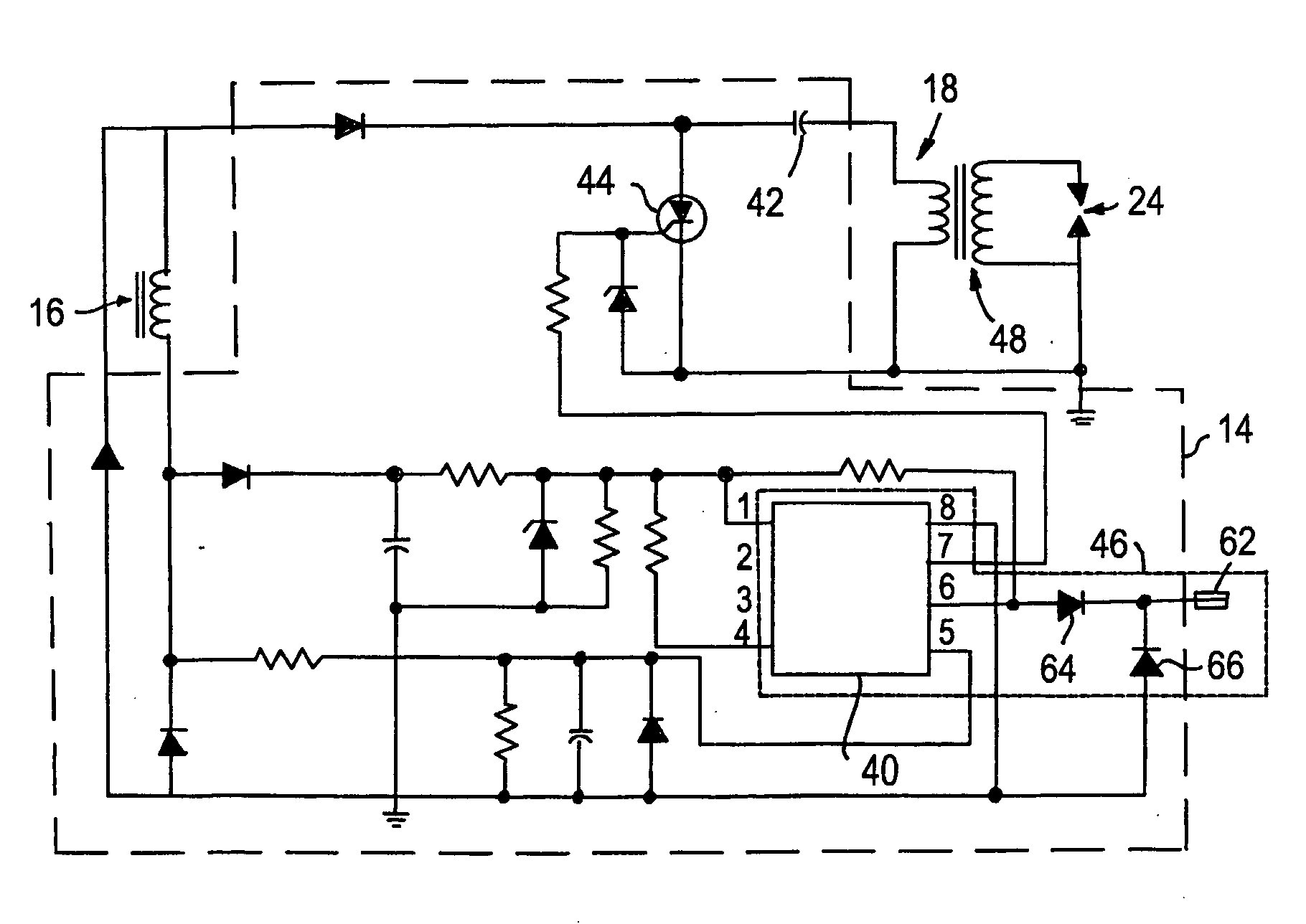
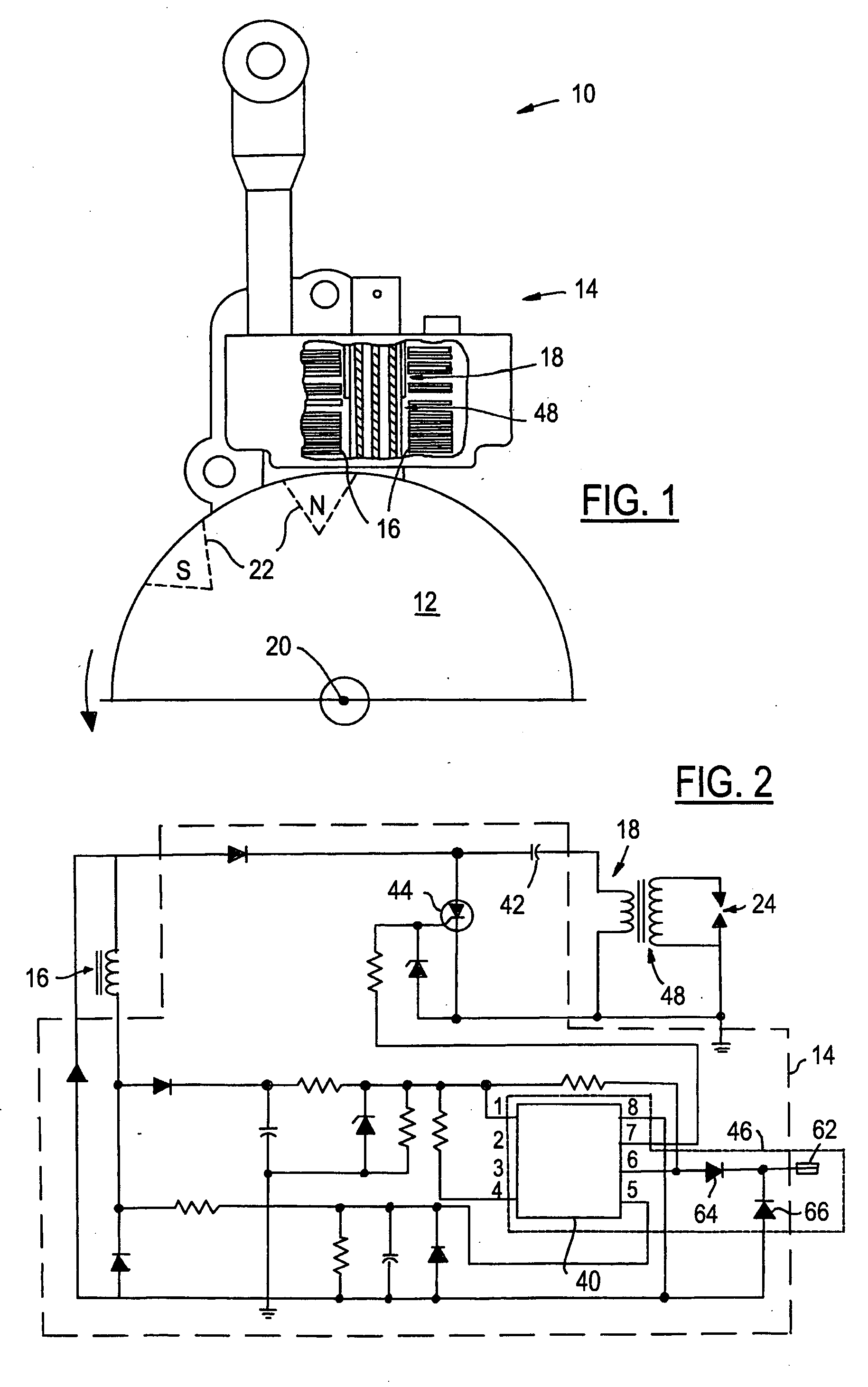
[0015] Referring to FIG. 1, there is shown an example of an ignition system 10 for a light-duty combustion engine that can utilize kill-switch control circuits and controlled shut down methods of the present invention. Ignition system 10 is preferably a capacitive discharge ignition system that interacts with a flywheel 12 and generally includes an ignition timing circuit 14, an input winding 16, and a primary winding 18. The flywheel 12 is coupled to an engine crankshaft (not shown) and rotates about an axis 20 under the power of the engine. By using its rotational inertia, the flywheel moderates fluctuations in engine speed, thereby providing a more constant and even output. Flywheel 12 includes magnetic sections 22 located near an outer circumference of the flywheel. Once the flywheel is rotating, these magnetic sections 22 spin past and electromagnetically interact with input winding 16 so that a voltage proportional to the rotational speed of flywheel 12, and h...


PUM


Abstract

A kill-switch control circuit for use with a light-duty combustion engine determines whether to execute a controlled shut down method or an immediate shut down method in response to kill-switch activation. The selection of a shut down method is made, at least in part, by using engine speed readings and by counting engine revolutions. The controlled shut down method utilizes ignition timing delay and / or spark ratio techniques to quickly bring the engine to a stop, yet does so in a controlled manner that avoids backfiring and other undesirable effects. Conversely, the immediate shut down method abruptly stops sending a current to the spark plug.

Description

FIELD OF THE INVENTION [0001] The present invention generally relates to ignition systems for internal combustion engines, and more particularly, to control circuits and methods for shutting down a combustion engine in a controlled manner. BACKGROUND OF THE INVENTION [0002] Internal combustion engines commonly have kill-switches incorporated into their ignition systems so that manual or automatic activation of the kill-switch results in an immediate shut down of the engine. Various types of kill-switches and accompanying circuitry have been utilized across a variety of applications, including light-duty combustion engines. The term ‘light-duty combustion engine’ used herein broadly includes all types of non-automotive combustion engines, including two- and four-stroke engines used with hand-held power tools, lawn and garden equipment, lawnmowers, weed trimmers, edgers, chain saws, snowblowers, personal watercraft, boats, snowmobiles, motorcycles, all-terrain-vehicles, etc. [0003] Un...

Claims


Application Information

Patent Timeline
Patent Type & Authority Applications(United States)
IPC IPC(8): F02P11/00F02D17/00G06F19/00
CPCF02D41/042F02D2400/06F02P1/086Y02T10/46F02P5/1504F02P11/02F02P11/025F02P3/083Y02T10/40
Inventor ANDERSSON, MARTIN N.PATTULLO, GEORGE M.
Owner WALBRO LLC
Why Eureka
Try Eureka