Method of reducing exhaust gas emissions during cold start conditions and an internal combustion engine in which the method is used

a technology of exhaust gas emissions and internal combustion engine, which is applied in the direction of machines/engines, electrical control, mechanical equipment, etc., can solve the problems of catalyst reaching the light off temperature more quickly, increasing the pressure difference between the in-cylinder pressure and the pressure inside the injector, and reducing the efficiency of the catalyst. , to achieve the effect of reducing the pressure difference, reducing the risk of catalyst oxidation, and improving the mixing of fuel

Inactive Publication Date: 2006-10-24
FORD GLOBAL TECH LLC
View PDF31 Cites 8 Cited by
  • Summary
  • Abstract
  • Description
  • Claims
  • Application Information

AI Technical Summary

Benefits of technology

[0006]By opening the intake valve late, that is after the piston has passed its top dead center position, an expansion of the combustion chamber takes place while the intake valve is closed. When opening the intake valve, the intake air enters into the combustion chamber under high velocity, even up to sonic conditions. Thus, the air enters into the cylinder at a velocity equal to the speed of sound. The high velocity enhances mixing of the fuel and supports breaking up the injected fuel droplets into smaller particles. Furthermore, by injecting fuel during the pressure drop, a larger pressure difference between the in-cylinder pressure and the pressure inside the injector exists. This increase in pressure difference mitigates the problem that the injector assembly has not yet reached its operating pressure.
[0007]According to a preferred embodiment of the invention, the fuel injection is divided into a main injection and at least one supplementary injection. A main part of the main injection takes place during the pressure drop and a supplementary injection takes place immediately before ignition takes place. By arranging a supplementary injection immediately before the ignition takes place it is possible to stabilize the combustion. Since the injection is positioned in time immediately before the ignition takes place, a local area of a rich air fuel mixture will be present at the spark plug. Using a supplementary injection facilitates stable combustion while having a total air fuel mixture in the combustion chamber, which is lean.
[0008]By providing a supplementary late injection, it is possible to delay ignition. Preferably, the combustion timing is retarded, such that 50% of the heat release occurs between 45° and 135° after a top dead center position of a piston arranged in the cylinder. Late combustion contributes to the reduction of hydrocarbon emissions during cold start for the following reasons. When the combustion takes place at a late stage, a larger portion of the combustion can take place with an open exhaust valve. This leads to a greater heat release to the catalytic converter in the exhaust channel, which in turn leads to that catalyst reaching its light off temperature more quickly. Furthermore, a larger portion of the cylinder walls are exposed to the flame. The amount of residual fuel adhered to the cylinder walls, which may be scraped off during the scavenging of the exhaust from the cylinder, is thereby correspondingly reduced.
[0009]According to a further preferred embodiment, the engine operates at high load during the cold start condition and at a high idling speed. By controlling the engine such that it works under high load, condensed fuel on the walls will have little effect on the mixing ratio between the air and the fuel, thereby resulting in that the lambda value of the air fuel mixture contained in the cylinder remains substantially constant. Under the condition of high load a high pressure is generated in the intake manifold. The high pressure counteracts a back flow into the manifold when the intake valve is open. Therefore, wall wetting in the intake manifold will be reduced. Pressure differences in the intake manifold during the operation of the engine will not give rise to large variations in lambda value, which may occur if a flow back from the cylinder into the intake manifold takes place, which flow back would lead to that fuel condensing at the walls of the intake manifold (wall wetting).

Problems solved by technology

Furthermore, by injecting fuel during the pressure drop, a larger pressure difference between the in-cylinder pressure and the pressure inside the injector exists.
This leads to a greater heat release to the catalytic converter in the exhaust channel, which in turn leads to that catalyst reaching its light off temperature more quickly.

Method used


Image

  • Method of reducing exhaust gas emissions during cold start conditions and an internal combustion engine in which the method is used
  • Method of reducing exhaust gas emissions during cold start conditions and an internal combustion engine in which the method is used
  • Method of reducing exhaust gas emissions during cold start conditions and an internal combustion engine in which the method is used

Examples


Embodiment Construction

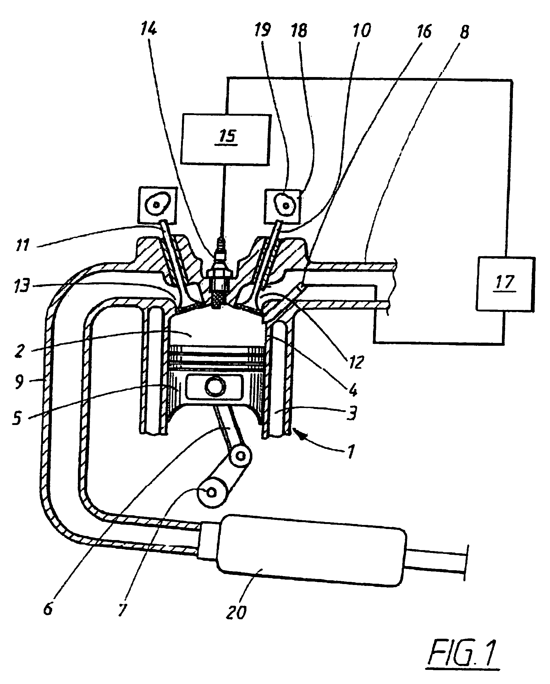
[0014]FIG. 1 show a spark ignition internal combustion engine. Engine 1 includes a set of combustion chambers 2, one of which is shown in the figure, formed in a cylinder block 3. The combustion chamber 2 is formed by a cylinder bore 4 in which a piston 5 is mounted. A connecting rod 6 transfers a reciprocating movement of the piston 5 into a rotational movement of a crank shaft 7.

[0015]The engine is further equipped with an intake conduit 8 and an exhaust conduit 9. The gas flow through the combustion chamber 2 is controlled by at least one intake valve 10 and at least one exhaust valve 11 arranged at an intake port 12 and exhaust port 13 providing a connection between the intake conduit 8 and the combustion chamber 2 respective between the combustion chamber 2 and the exhaust conduit.

[0016]Furthermore, the combustion chamber 2 is provided with ignition means 14 in the form of a spark plug which timing is controlled by an ignition system 15.

[0017]Fuel is injected by a fuel injector...


PUM


Abstract

An internal combustion engine and a method of reducing hydrocarbon emissions of an internal combustion engine during cold start conditions in disclosed. The engine has at least one cylinder provided with a piston which reciprocates between a top dead-center and a bottom dead-center, at least one intake valve through which intake air is provided, a fuel injector assembly arranged to inject atomised fuel particles directly into the cylinder and means for controlling the opening and closing of the intake valve. According to the invention, intake valve opening is adjusted to occur after top dead center of the piston. When the intake valve opens, a pressure differential exists across the valve. Fuel is injected directly into the cylinder during the time of the pressure differential.

Description

FIELD OF THE INVENTION[0001]The invention relates to a method for reducing exhaust gas emissions of an internal combustion engine during cold start conditions. The intake valve opens after top dead center position of the piston to create a pressure drop and fuel is injected during the pressure drop.BACKGROUND[0002]Legislation relating to environmental protection puts an increasing restrictions on emissions from combustion engines. For this reason, modern vehicles are equipped with catalysts at which hydrocarbons are converted into water and carbon dioxide. A catalyst must have reached its operating temperature to operate efficiently. Many attempts have been made to reduce the time needed for catalysts to reach their light off temperature. Even though some of these attempts have been successful and the time needed to reach light off temperature has been reduced, starts and, in particular, cold starts are still responsible for a great proportion of total emissions of hydrocarbons from...

Claims


Application Information

Patent Timeline
Patent Type & Authority Patents(United States)
IPC IPC(8): F02B3/02F01L1/34F02D41/00F02D41/06F02D41/16F02D41/40
CPCF02D41/0002F02D41/064F02D41/402F02D41/16F02D2041/001F02D2041/389Y02T10/44Y02T10/42Y02T10/18Y02T10/12Y02T10/40
Inventor ALMKVIST, GORANSANDQUIST, HAKANHAKANSSON, HENRIK
Owner FORD GLOBAL TECH LLC
Why Eureka
Try Eureka