Combination air pressure system and plasma ion gas generator system for turbocharged diesel engine

a plasma ion gas and turbocharged technology, which is applied in the direction of machines/engines, combustion air/fuel air treatment, mechanical equipment, etc., can solve the problems of complex and expensive apparatus and methods, which are not disclosed in prior art references, and achieve the effect of increasing mileage per gallon and being convenient to install

Inactive Publication Date: 2013-10-01
CFT GLOBAL
View PDF6 Cites 7 Cited by
  • Summary
  • Abstract
  • Description
  • Claims
  • Application Information

AI Technical Summary

Benefits of technology

[0007]In view of the foregoing, it is a primary objective of the subject invention to provide an air pressure system incorporated into an ionized plasma gas generator system that is inexpensive, easy to install under the hood of a truck, tractor with trailer and similar type of vehicles and next to a diesel engine. The combination of the two systems supplies air under pressure to a gas mixture. The pressurized gas mixture is then introduced into the engine's intake manifold for increasing mileage per gallon in a range of 10 to 25% and greater during highway use. The combination of systems can also be used with mobile and stationary engines. While the invention is discussed herein used with a diesel engine, it can also be used with bio-diesel, compressed natural gas, powdered coal, and gasoline operated vehicles. Also, the systems can be used independently or in conjunction with other power sources to provide the gas mixture to other power generating systems, such as fuel cells, steam engines, hydrogen engines or for other uses, such as heating ovens, ranges and infared catalytic heaters.

Problems solved by technology

These patents disclose complex and expensive apparatus and methods for generating hydrogen gas using an electrolysis cell and require a major redesign of a standard diesel engine and the engine's exhaust system.
None of these prior art references disclose the unique combination of an air pressure system with a plasma ion gas generator system used for overcoming an air intake pressure into the intake manifold of a diesel fuel engine and similar applications.

Method used


Image

  • Combination air pressure system and plasma ion gas generator system for turbocharged diesel engine
  • Combination air pressure system and plasma ion gas generator system for turbocharged diesel engine

Examples


Embodiment Construction

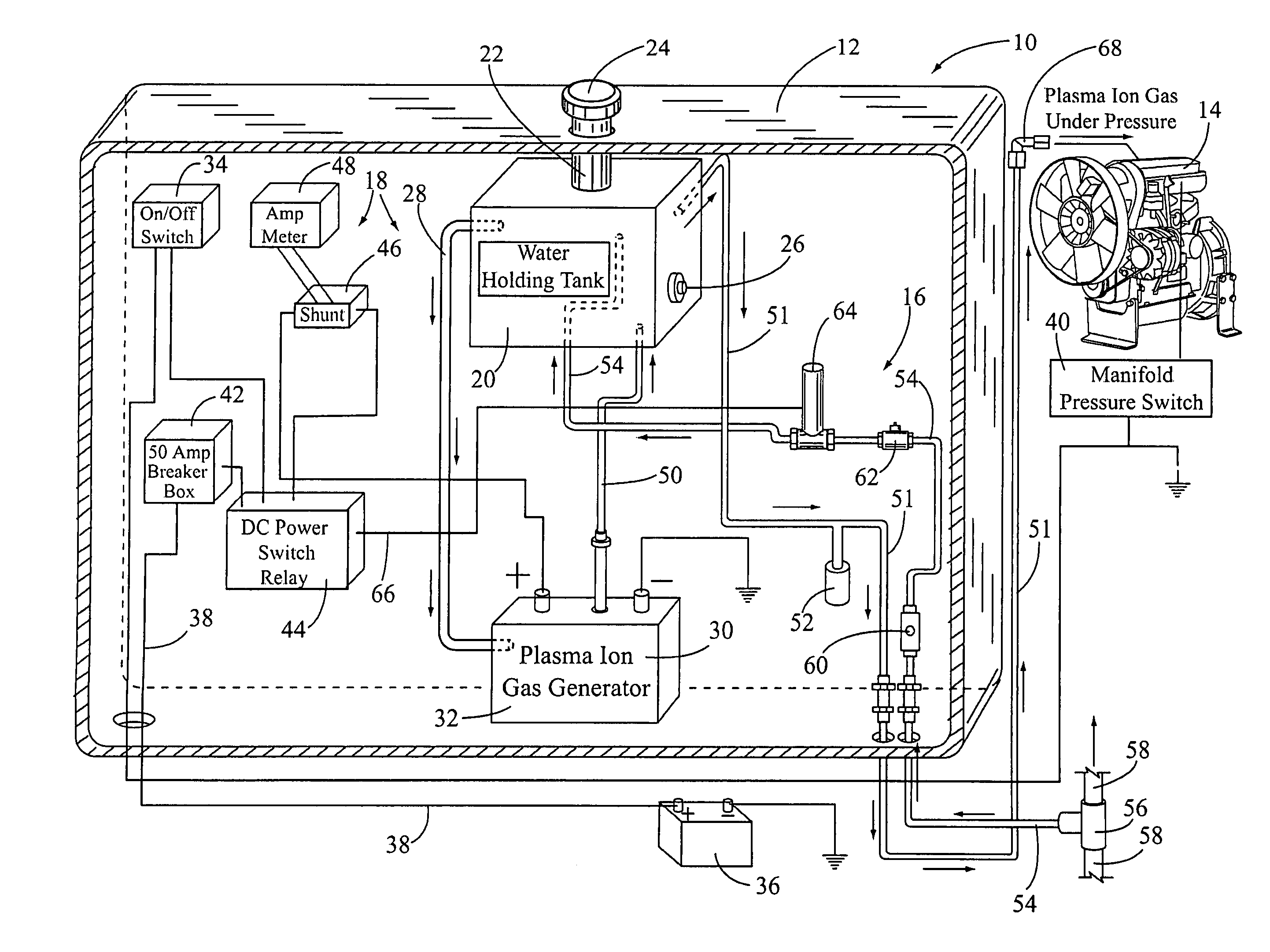
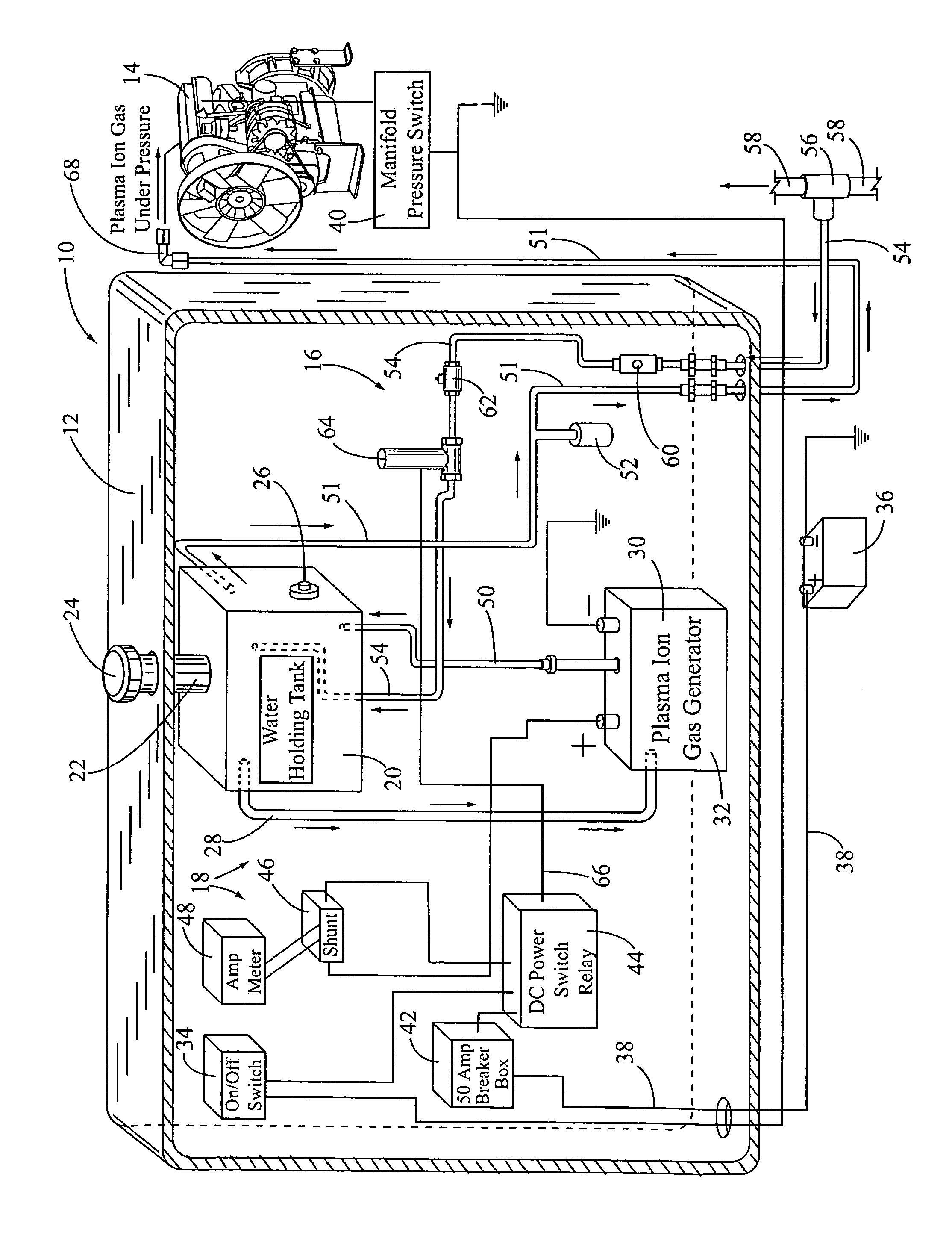
[0014]In FIG. 1, the subject combination air pressure and plasma ion gas generator system is shown having general reference numeral 10. The combination system 10 is mounted in a system housing 12 and adapted for introducing a gas mixture under pressure to an intake manifold of a turbocharged diesel engine 14. The combination system includes air pressure system, having a general reference numeral 16 and a plasma ion gas generator system, having a general reference numeral 18.

[0015]The plasma ion gas generator system 18 includes a water holding tank 20 with a water fill port 22, a fill cap 24 in the top of the housing 12, and a water level indicator 26 in the side of the tank 20. The water level indicator 26 is used to indicate low water in the system 18. The water holding tank 20 typically holds from 2 to 20 gallons of fluid. The tank 20 is used to feed distilled water, via a water line 28, into a side of a plasma ion gas generator 30 having a generator housing 32 with a plurality of...


PUM


Abstract

A combination air pressure system and a plasma ion gas generator system adapted for mounting next to an intake manifold of a turbocharged diesel engine. The system includes a water holding tank for supplying water to a plasma ion gas generator. The gas generator includes a housing with a plurality anode and cathode electrode plates. The system also includes an on/off switch and amp meter. The on/off switch is connected to the vehicle's battery. When the system is turned “on”, power is supplied to the gas generator for generating combustible gases. The air pressure system includes an air line connected to a vehicle's high pressure air line. The system's air line is connected to the water holding tank for pressurizing the gas mixture before it's introduced in the intake manifold.

Description

[0001]This non-provisional patent application is a continuation-in-part patent application of a patent application Ser. No. 13 / 068,766, filed on May 20, 2011, having a title of “Ionized Plasma Gas Generator System for an Internal Combustion Engine”, by the subject inventors.BACKGROUND OF THE INVENTION[0002](a) Field of the Invention[0003]This invention relates to a combination of systems for introducing gases under pressure into an intake manifold of a turbocharged diesel engine and more particularly, but not by way of limitation, to an air pressure system adapted for mounting on a vehicle and next to a vehicle's diesel engine for overcoming manifold intake air pressure, when supplying a mixture of plasma ion gas into the intake manifold of the engine. The mixture of the plasma ion gas including hydrogen gas, oxygen gas, Brown's gas, HHO, nascent hydrogen and oxygen gas, and hydrinos sufficient to enhance diesel fuel introduced into the intake manifold. The mixture of gases introduc...

Claims


Application Information

Patent Timeline
Patent Type & Authority Patents(United States)
IPC IPC(8): F02B43/10
CPCF02B43/10F02M25/12Y02T10/121Y02T10/12
Inventor GALVIN, PATRICKERSTIENS, KENNY
Owner CFT GLOBAL
Why Eureka
Try Eureka