Fuel injector designed to optimize pattern of fuel spray

Active Publication Date: 2005-10-27
DENSO CORP
View PDF19 Cites 8 Cited by
  • Summary
  • Abstract
  • Description
  • Claims
  • Application Information

AI Technical Summary

Benefits of technology

[0013] It is another object of the invention to provide an inexpensive and simple structure of a fuel injector designed to avoid rich misfire and reduce HC emissions from an internal combustion engine regardless of the intake asynchronous and synchronous injection modes.
[0014] According to one aspect of the invention, there is provided a fuel injector which may be employed in automotive internal combustion engines. The fuel injector comprises: (a) an injector body having a fuel outlet; and (b) a spray hole formed in the fuel outlet. The spray hole are geometrically designed to produce a spray of fuel in a predetermined pattern so that substantially 70% or more of an amount of the spray hits a preselected area on a surface of a head of an intake valve of an engine when the intake valve is closed. The preselected area is one of a first and a second area on the surface of the head of the intake valve which are d

Problems solved by technology

This results in an decreased amount of fuel adhered to an inner bottom wall of the intake manifold near an intake port even in an intake as

Method used


Image

  • Fuel injector designed to optimize pattern of fuel spray
  • Fuel injector designed to optimize pattern of fuel spray
  • Fuel injector designed to optimize pattern of fuel spray

Examples


first embodiment

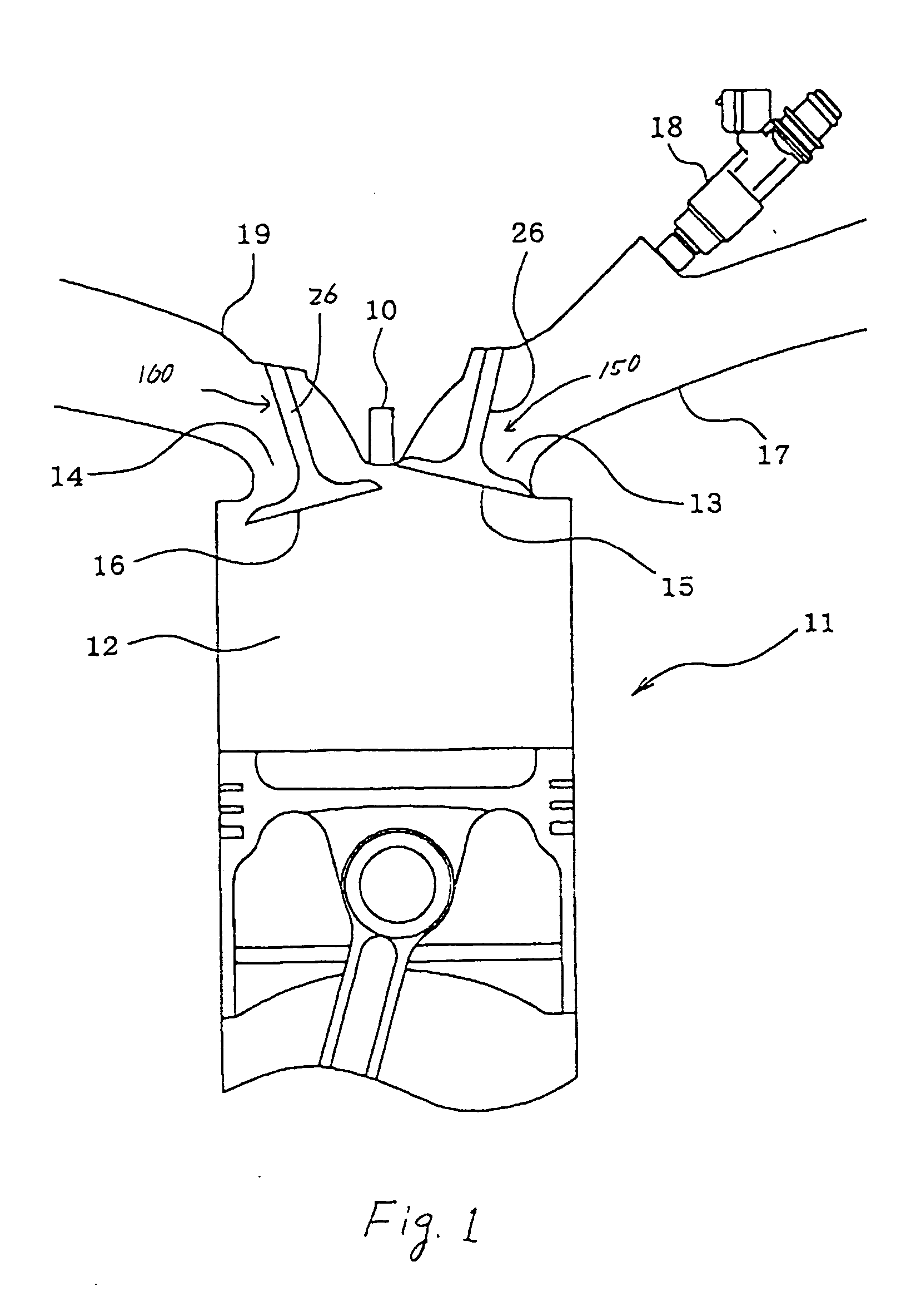
[0083] Referring to the drawings, wherein like reference numbers refer to like parts in several views, particularly to FIGS. 1 to 8, there is shown a fuel injector according to the invention which is implemented in this and other embodiments, as will be discussed later, by, for example, a fuel injection valve working to inject fuel to an internal combustion engine 11.

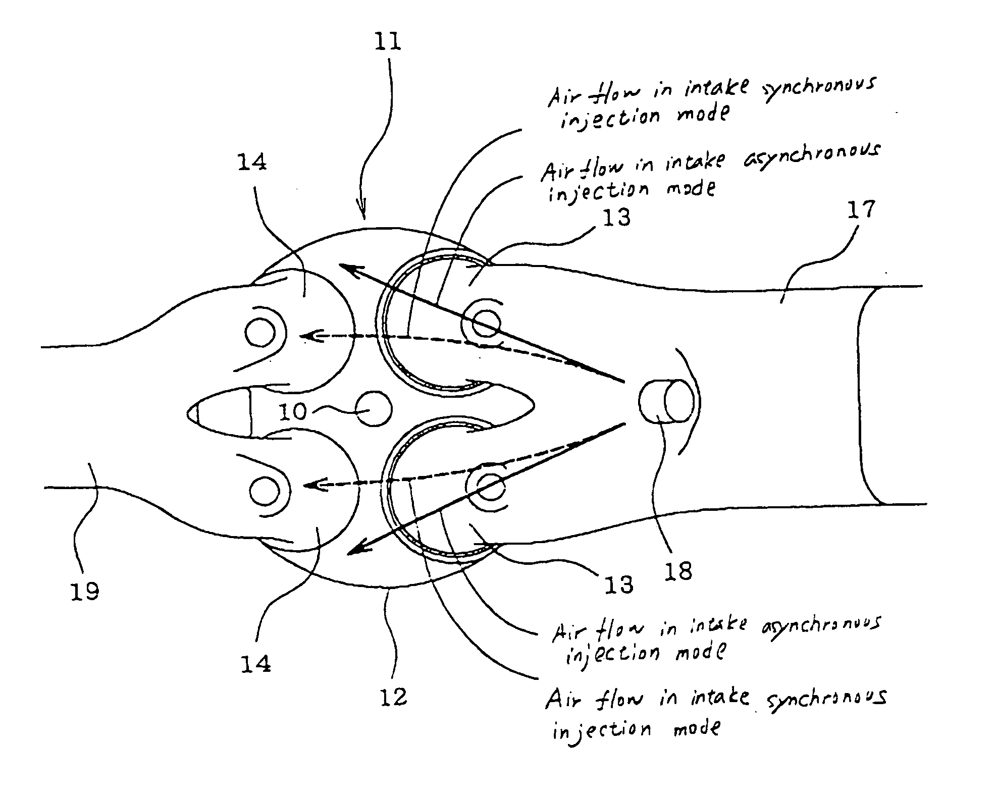
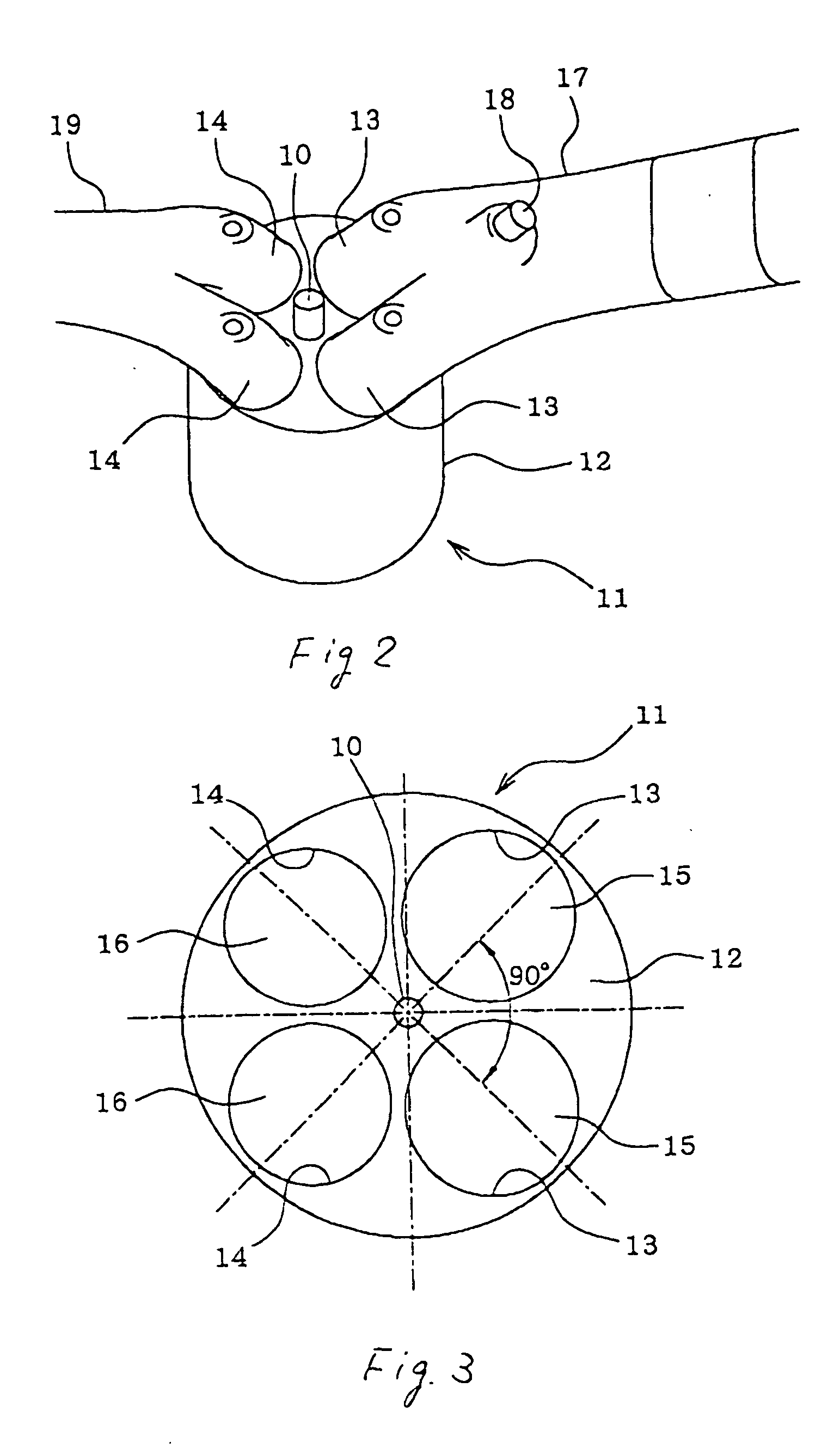
[0084] The engine 11 has, for example, two intake ports 13 and two exhaust ports 14 which are arrayed at intervals of 90°, as clearly shown in FIG. 3, around a spark plug 10 installed in the center of an upper wall of a combustion chamber 12. The intake ports 13 are opened or closed by heads 15 of intake valves150. Similarly, the exhaust ports 14 are opened or closed by heads 16 of exhaust valves 160. To the intake ports 13, branches of an intake manifold 17 are connected. The fuel injection valve 18 is installed upstream of a branch connection of the intake manifold 17. To the exhaust ports 14, branches of an exhaust m...

second embodiment

[0095] The fuel injection valve 18 according to the invention will be described below with reference to FIGS. 9 to 10(b).

[0096] In the intake synchronous injection mode, streams of air flowing through the two intake ports 13 opening into the combustion chamber 12 are, as can be seen in FIG. 9, usually susceptible to divergence to the longitudinal center line of the combustion chamber 12 (i. e., the spark plug 10). This causes sprays of fuel from the fuel injection valve 18 to be oriented toward the longitudinal center line of the combustion chamber 12 from target areas of the heads 15 of the intake valves 150, so that much fuel sticks to the inner wall of the combustion chamber 12 near the exhaust ports 14 and then discharged without being burned, thus resulting in an increased amount of HC emissions.

[0097] In order to alleviate the above problem, the fuel injection valve 18 of this embodiment is designed to orient jets of fuel, as clearly shown in FIG. 10(b), to dark areas of the ...

third embodiment

[0098] The fuel injection valve 18 will be described below which is equipped with an air assist feature which assists in enhancing atomization of fuel using an air jet or a heating feature which does it using thermal energy produced by a heater. The air assist feature or the heating feature can be of any known type designed to start and stop production of the air jet selectively or turn on and off a heater selectively. For example, Japanese Patent First Publication No. 4-159452 discloses an example of the air assist feature. Japanese Patent First Publication No. 2003-314402 teaches an example of the heating feature. Either of these may be employed in this embodiment.

[0099] A spray pattern of the fuel injection valve 18 greatly depends upon activities of the air assist feature or the heating feature. Use of the air assist feature or the heating feature serves to facilitate the atomization of fuel sprayed from the fuel injection valve 18, thereby improving burning of the fuel in the ...


PUM


Abstract

A fuel injector for an internal combustion engine which has a spray hole designed geometrically to produce a spray of fuel so that substantially 70% or more of an amount of the spray hits a preselected area of a head of an intake valve of the engine when the intake valve is closed. The preselected area is one of a first and a second area of the intake valve head which are defined by a reference boundary line extending through a base end of a stem of the intake valve. The preselected area is the first area closer to an intake manifold, while the second area is closer to an exhaust valve. This avoids rich misfire and reduces HC emissions from the engine regardless of the intake valve is in a closed state or in an open state.

Description

CROSS REFERENCE TO RELATED DOCUMENT [0001] The present application claims the benefit of Japanese Patent Application No. 2004-127924 filed on Apr. 23, 2004, the disclosure of which is incorporated herein by reference. BACKGROUND OF THE INVENTION [0002] 1. Technical Field of the Invention [0003] The present invention relates generally to a fuel injector designed to inject fuel into an internal combustion engine in an unique spray pattern, and more particularly to an improved structure of such a fuel injector designed to optimize the pattern of a spray of fuel when hitting a head of an intake valve of the engine. [0004] 2. Background Art [0005] Japanese Patent Publication Nos. 6-101603 and 4-121435 disclose an injector orientation changing mechanism which is installed in an intake manifold of an internal combustion engine to change the direction in which fuel is sprayed from a fuel injector to an intake port based on operating conditions of the engine in order to optimize the pattern ...

Claims


Application Information

Patent Timeline
IPC IPC(8): F02M51/06F02D41/04F02D41/06F02M35/10F02M53/04F02M61/14F02M61/18F02M69/04
CPCF02B2275/16F02M35/10216F02M35/1085F02M61/145Y02T10/123F02M61/1826F02M61/1853F02M69/044F02M61/1806Y02T10/12
Inventor KAYAMA, RYOZOSUZUKI, HIDEKIMATSUO, TETSUHARUTOMIITA, YUKIO
Owner DENSO CORP
Why Eureka
Try Eureka