Low temperature catalyst/hydrocarbon trap

a low temperature catalyst and hydrocarbon trap technology, which is applied in the direction of physical/chemical process catalysts, arsenic compounds, separation processes, etc., can solve the problems of reducing the adsorption capacity of hydrocarbons, affecting the adsorption efficiency of hydrocarbons, etc., to achieve good hydrocarbon adsorption capability and reduce cold-start vehicle emissions

Active Publication Date: 2015-08-20
FORD GLOBAL TECH LLC
View PDF4 Cites 9 Cited by
  • Summary
  • Abstract
  • Description
  • Claims
  • Application Information

AI Technical Summary

Benefits of technology

[0009]Those needs are met by embodiments of the invention which provide a catalyst / hydrocarbon trap for reduction of cold-start vehicle emissions of gasoline and diesel engines or engines using bio-fuels. The catalyst / hydrocarbon trap includes an oxygen storage capacity (OSC) material therein to provide sufficient oxygen to achieve oxidation of hydrocarbons and carbon monoxide (CO) at low temperatures. The catalyst / hydrocarbon trap is positioned in a vehicle exhaust system such that the exhaust temperatures are maintained at a temperature below 850° C., and preferably, below 700° C. during normal vehicle operation to maintain good hydrocarbon adsorption capability for the full useful life of the exhaust system.
[0016]According to another aspect of the invention, a method for reducing cold start hydrocarbon emissions from a vehicle engine is provided in which the low-temperature catalyst / hydrocarbon trap is positioned in the exhaust passage of a vehicle downstream from a close-coupled catalyst and exhaust gases are passed through the catalyst / trap. In one embodiment, the temperature of the exhaust gas stream, when in contact with the trap, does not exceed 700° C. during normal vehicle cperation. Preferably, the temperature of the exhaust gas stream is at least 400° C. during normal vehicle operation. As exhaust gases are passed through the exhaust passage, the trap adsorbs unburned hydrocarbon emissions in the exhaust and retains the hydrocarbons until sufficient temperatures are reached for catalytic conversion, i.e., from about 200° C. to about 600° C. At least a portion of unburnt hydrocarbons and / or carbon monoxide which are not absorbed in the trap during cold-start are oxidized by the low-temperature catalyst at a temperature less than about 200° C.

Problems solved by technology

However, during initial starting of the engine, the three-way catalysts are not sufficiently hot to become catalytically active, i.e., they have not reached their “light-off” temperature.
As a result, pollutants may pass through the engine exhaust system without being treated.
One of the greatest challenges with the use of such hydrocarbon traps in an exhaust system is to retain the adsorbed hydrocarbons until the three-way catalyst is hot enough to efficiently convert the HC when desorbed from the trap.
Hence, oxygen is significantly depleted from the exhaust stream by oxidation reactions occurring over the close-coupled TWC catalyst, so there is often insufficient oxygen left to react with the released HC from the trap to form CO2 and H2O.
This can cause HC to slip out of the trap untreated, resulting in low HC conversion.
These problems increase with the aging of the trap.
For example, high temperature aging during vehicle operation causes stored hydrocarbons to desorb at lower temperatures and requires higher temperatures to achieve oxidation of the released hydrocarbons.
While lower operating temperatures have been achieved by placing the a hydrocarbon trap in the underbody converter assembly of the vehicle, exhaust gas oxygen required to enable conversion of trapped HC to CO2 and H2O is limited in this location.
While gamma alumina and zeolites have been used in conventional hydrocarbon traps, they tend to lose adsorption capability at such high temperatures.

Method used


Image

  • Low temperature catalyst/hydrocarbon trap
  • Low temperature catalyst/hydrocarbon trap
  • Low temperature catalyst/hydrocarbon trap

Examples


example 1

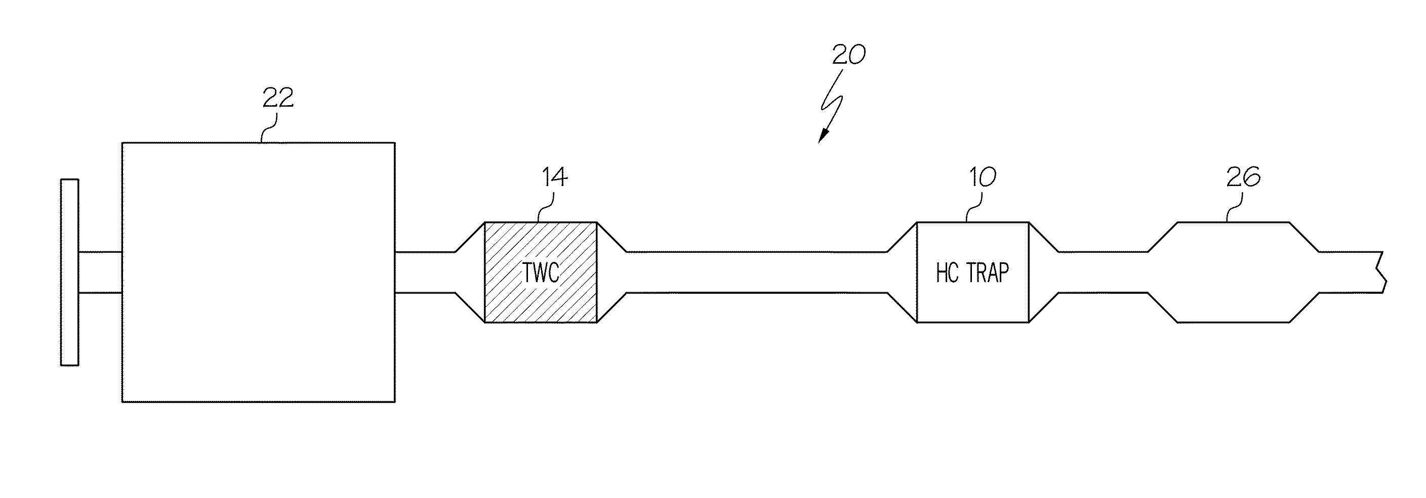
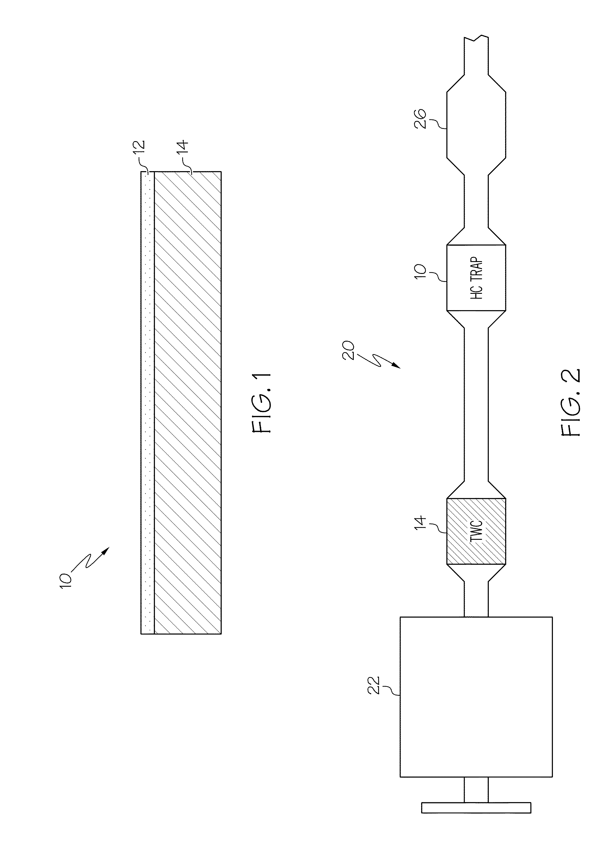
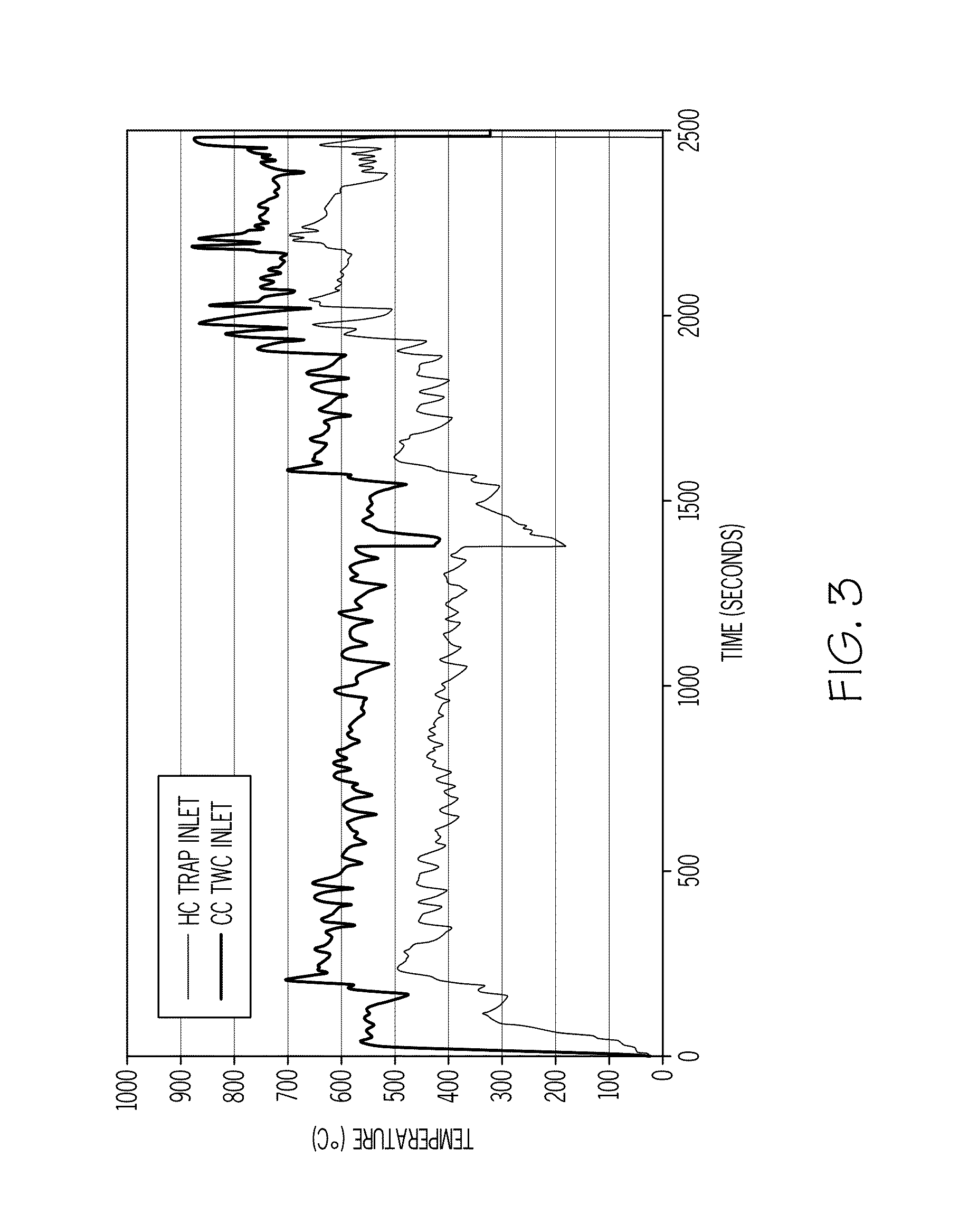
[0048]The emissions from two conventional TWC catalysts and two underbody hydrocarbon traps were measured from the exhaust of a 2.0 liter Ford Focus vehicle during combined FTP and US06 drive cycles, run on a chassis-roll dynamometer. The hydrocarbon traps were positioned approximately 40 inches downstream from a close-coupled three-way catalyst and approximately 57 inches from the exhaust manifold header flange. The FTP (Federal test procedure) drive cycle is used to determine whether a catalyst system can meet regulated emissions standards on a specific vehicle. The US06 drive cycle is a test cycle that is used to represent highway driving where the vehicle operates at higher speed and load conditions than what may be typical of less aggressive drive cycles. FIG. 3 illustrates the exhaust temperatures measured on the vehicle at the close-coupled TWC and underbody HC trap locations during the combined test cycles. As can be seen, due to positioning of the traps, the temperature of ...

example 2

[0049]A catalyst formulation was prepared in accordance with an embodiment of the invention. About 1.5 wt % palladium was dispersed on a CZO support at a weight ratio of 75:25. The catalyst was subjected to laboratory tests in comparison with a conventional catalyzed hydrocarbon trap which was prepared by coating a cordierite monolith support with a zeolite slurry, followed by a heat treatment, coating with a TWC slurry, followed by calcination, then coated with a TWC catalyst and heat treated, and then impregnated with a PGM solution. The HC trap further included a CZO material containing greater than 60% by weight zirconia. The conventional HC trap was designed for aging conditions up to 1000° C. which would typically be encountered in an engine under normal aging conditions.

[0050]The aging conditions for both samples consisted of a 4-mode cycle where the sample midbed temperature was an effective (weighted average) of 760° C. (range of 740° C. to 840° C.) for 50 hours in sulfur-f...

example 3

[0052]A catalyst formulation was prepared as in Example 2 including palladium on a CZO support including zeolite (hydrocarbon trap). The trap was positioned downstream from a bed of beta zeolite having an Si / Al2 ratio of 25 (Zeolyst CP814E). The trap was evaluated for desorption of ethanol in comparison with a conventional hydrocarbon trap including a catalyst and CZO material as described in Example 2. The samples were subjected to a feed containing ethanol at 900 ppm for 30 seconds, followed by removal of ethanol from the feed. The samples were then heated and tested for outlet emissions as a function of outlet temperature.

[0053]As can be seen, ethanol desorption occurred at temperatures between 100° C. to 350° C. during warm-up of the catalyst. As shown in FIG. 5, the hydrocarbon trap comprising palladium on the CZO material oxidized more than 90% of the stored ethanol to CO2 and 8% to CH4 with almost no unconverted ethanol slipping out.

[0054]As shown in FIG. 6, in the convention...


PUM

PropertyMeasurementUnit
exhaust gas temperatureaaaaaaaaaa
temperatureaaaaaaaaaa
exhaust gas temperatureaaaaaaaaaa

Abstract

A low-temperature catalyst is provided for reducing cold-start hydrocarbon emissions. The catalyst comprises a platinum group metal impregnated onto an oxygen storage material. The catalyst may be used alone or may be included in a hydrocarbon trap containing a hydrocarbon adsorption material therein. The catalyst / hydrocarbon trap is positioned in the exhaust system of a vehicle downstream from a close-coupled catalyst such that the exhaust temperature at the catalyst location does not exceed 850° C. during normal vehicle operation and when combined with a hydrocarbon adsorption material in a trap, the exhaust temperature does not exceed 700° C.

Description

BACKGROUND OF THE INVENTION[0001]Embodiments described herein relate to a catalyst for cold-start engine emissions which contains oxygen storage materials to provide a source of oxygen for hydrocarbon combustion at low temperatures. More particularly, embodiments described herein relate to a hydrocarbon trap including the catalyst.[0002]In recent years, considerable efforts have been made to reduce the level of carbon monoxide (CO), hydrocarbon (HC), and nitrogen oxide (NOx) emissions from vehicle engines. Conventional exhaust treatment systems typically include a three-way catalyst (TWC) to reduce these pollutants and prevent the exit of unburnt or partially burnt hydrocarbon emissions from the vehicle exhaust. However, during initial starting of the engine, the three-way catalysts are not sufficiently hot to become catalytically active, i.e., they have not reached their “light-off” temperature. As a result, pollutants may pass through the engine exhaust system without being treate...

Claims


Application Information

Patent Timeline
Patent Type & Authority Applications(United States)
IPC IPC(8): B01D53/94B01J35/04B01J23/63B01J29/068B01J23/10
CPCB01D53/9486B01D53/94B01J29/068B01J23/10B01D2255/1023B01J35/04B01D2255/50B01D2255/407B01J23/63B01D53/945B01D53/9477B01D2255/908B01D2255/909B01J29/44B01J29/7007B01J29/7415B01J35/0006B01J37/0246Y02A50/20Y02T10/12
Inventor XU, LIFENGMCCABE, ROBERT WALTERLUPESCU, JASON AARON
Owner FORD GLOBAL TECH LLC
Why Eureka
Try Eureka