Solder ball terminal

a technology of solder ball and terminal, which is applied in the direction of fixed connections, sustainable manufacturing/processing, and final product manufacturing, etc., can solve the problems of solder ball misalignment, difficult design of offset connectors, and solder ball misalignmen

Inactive Publication Date: 2002-03-05
TATE JOHN O
View PDF20 Cites 69 Cited by
  • Summary
  • Abstract
  • Description
  • Claims
  • Application Information

AI Technical Summary

Problems solved by technology

For instance, due to the offset design, the alignment of the connector is complicated and, once the connections are made, the offset connector can be difficult to design around.
Furthermore, the offset design, in combination with the irregular shape of the solder mass, introduces the possibility that the mass could be misaligned with the mounting pad, since the parallel portion might not always be precisely parallel and since the solder mass may not fit precisely on or in the mounting pad.
Although generally effective, there are several disadvantages to conventional solder ball terminals.
For example, the terminal can lack good mechanical security (and hence electrical continuity) since the solder ball can be prone to breaking off from the smooth, flat surface of the terminal.
Also, the shape (i.e. roundness) of the solder ball can be affected during the attachment of the ball to the terminal which, in turn, can adversely affect attachment to the mounting pad.
Proper alignment of the solder ball to the terminal can likewise be compromised during the attachment procedure.
Also, because the solder ball is attached to the end of the terminal, the distance between the terminal and the mounting pad prior to the application of heat to the solder ball is greater than the diameter of the solder ball, thus increasing the risk of the terminal becoming misaligned with the mounting pad while the solder ball is being liquefied.

Method used


Image

  • Solder ball terminal
  • Solder ball terminal
  • Solder ball terminal

Examples


Embodiment Construction

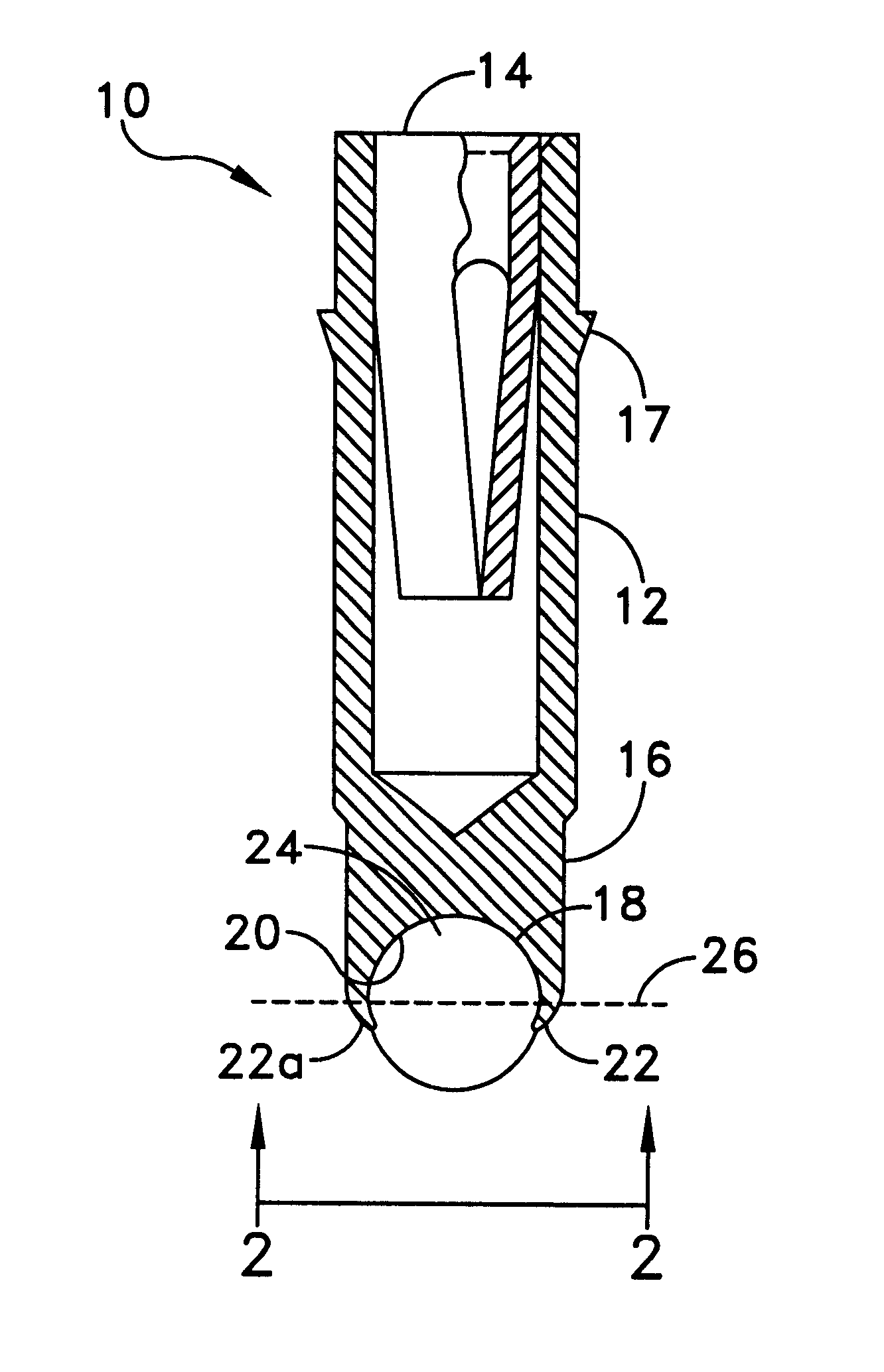
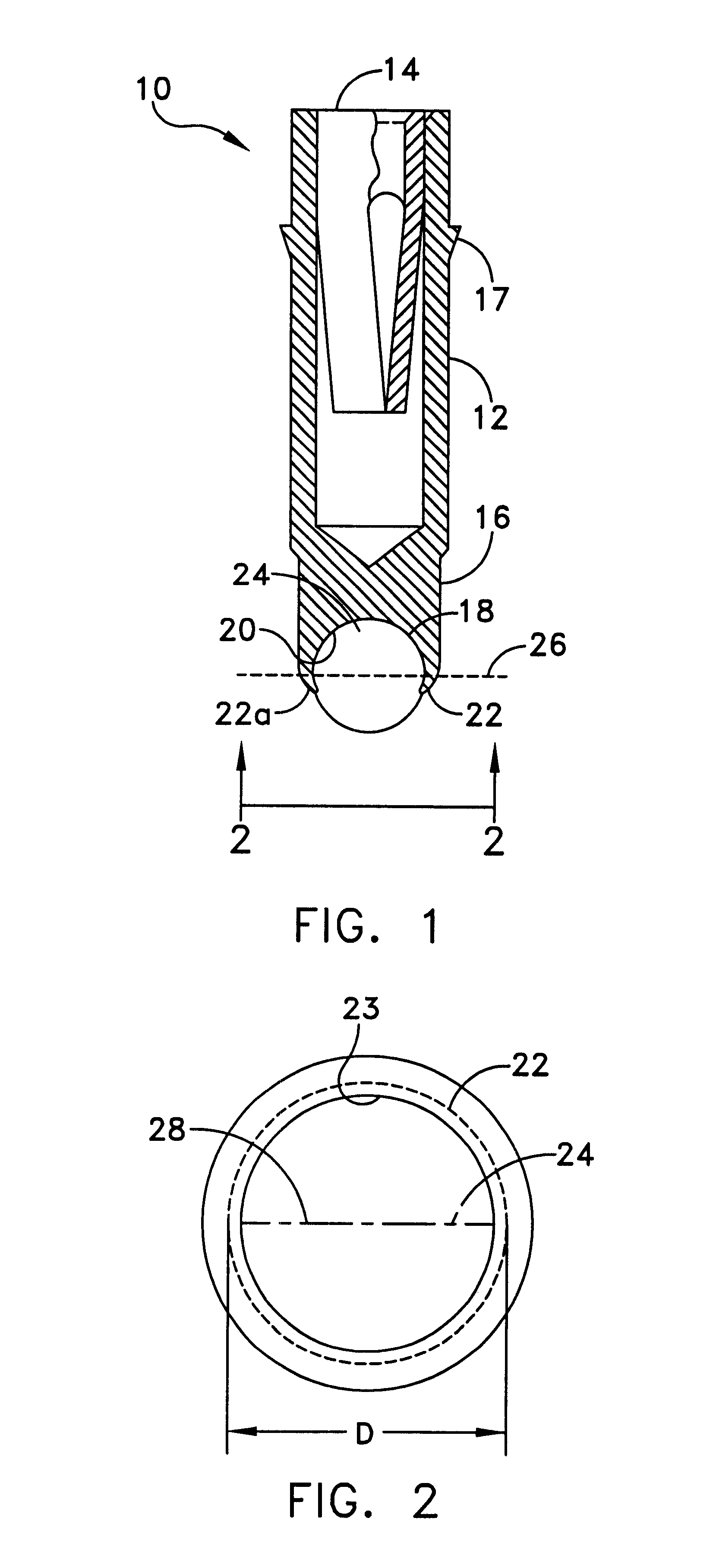
Referring now to the drawings, and more particularly FIGS. 1 and 2, there is generally indicated at 10 a solder ball terminal in accordance with the present invention. Solder ball terminal 10 includes a body portion 12 having a female socket 14 disposed at one end thereof and a head portion 16 disposed at an opposite end thereof. Preferably, the body 12, socket 14, and head 16 are formed from a unitary piece of metal.

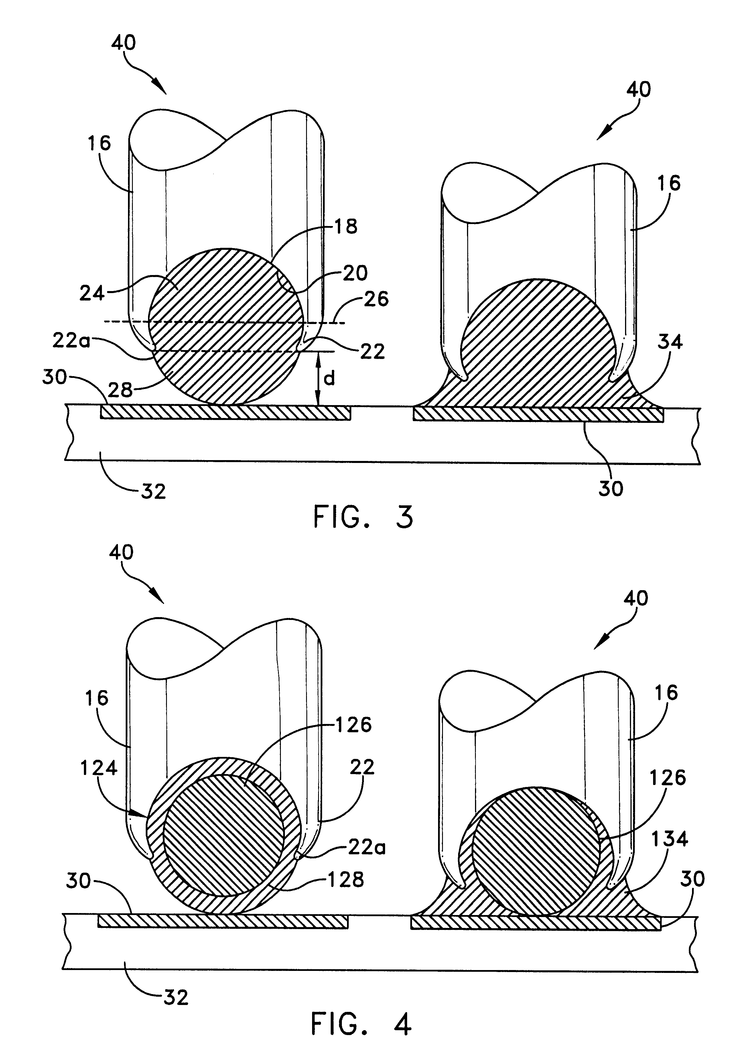
Head 16 further includes a connection socket 18 which is defined internally by a wall 20, and which includes an annular lip 22 located at the distal end of the head 16. The socket 18 may preferably be spherical so that a solder ball 24 can be easily fitted or swadged into the socket 18. The solder ball 24 is formed from typical solder materials, such as tin and lead, and the diameter of the solder ball 24 is approximately 0.020"-0.030" in the present embodiment. It should be understood that any size solder ball may be used in conjunction with the present invention, prov...


PUM


Abstract

A solder ball terminal includes a body portion, a spherical socket disposed at one end of the body portion, the spherical socket including an interior wall terminating in an annular lip, wherein the annular lip defines an opening of the spherical socket and a solder ball disposed within the socket such that a portion of the solder ball extends through the opening and beyond the annular lip.

Description

The present invention generally relates to electrical connectors and more particularly to a solder ball terminal which facilitates the connection of electrical leads to surface mount ball grid array devices, land grid array devices and board to board connections.DISCUSSION OF THE RELATED ARTIn the electronics equipment industry, it is known to provide leads for connection to contact pads of printed circuit boards and other substrates by soldering the leads thereto. However, as the electronics industry continues to move toward greater miniaturization, the size and spacing between the contact pads has accordingly been reduced. This requires a corresponding reduction in the size and spacing of the leads which are connected to contact pads. While the reduction of the spacing between the leads is advantageous from a space-conservation standpoint, it is important to provide sufficient spacing to prevent inadvertent contact between adjacent leads. It is likewise important to ensure that a ...

Claims


Application Information

Patent Timeline
Patent Type & Authority Patents(United States)
IPC IPC(8): H01R4/02H05K3/34H01R12/52
CPCH01R4/02H01R12/52H05K3/3426Y02P70/50
Inventor TATE, JOHN O.
Owner TATE JOHN O
Why Eureka
Try Eureka