Living body inspecting apparatus and noninvasive blood analyzer using the same

Inactive Publication Date: 2002-03-05
SYSMEX CORP
View PDF21 Cites 367 Cited by
  • Summary
  • Abstract
  • Description
  • Claims
  • Application Information

AI Technical Summary

Problems solved by technology

This raises a problem that it is not possible to obtain optical information from a blood vessel or tissue in a normal state.
This is because, if the portion of the living body is fixed

Method used


Image

  • Living body inspecting apparatus and noninvasive blood analyzer using the same
  • Living body inspecting apparatus and noninvasive blood analyzer using the same
  • Living body inspecting apparatus and noninvasive blood analyzer using the same

Examples


first embodiment

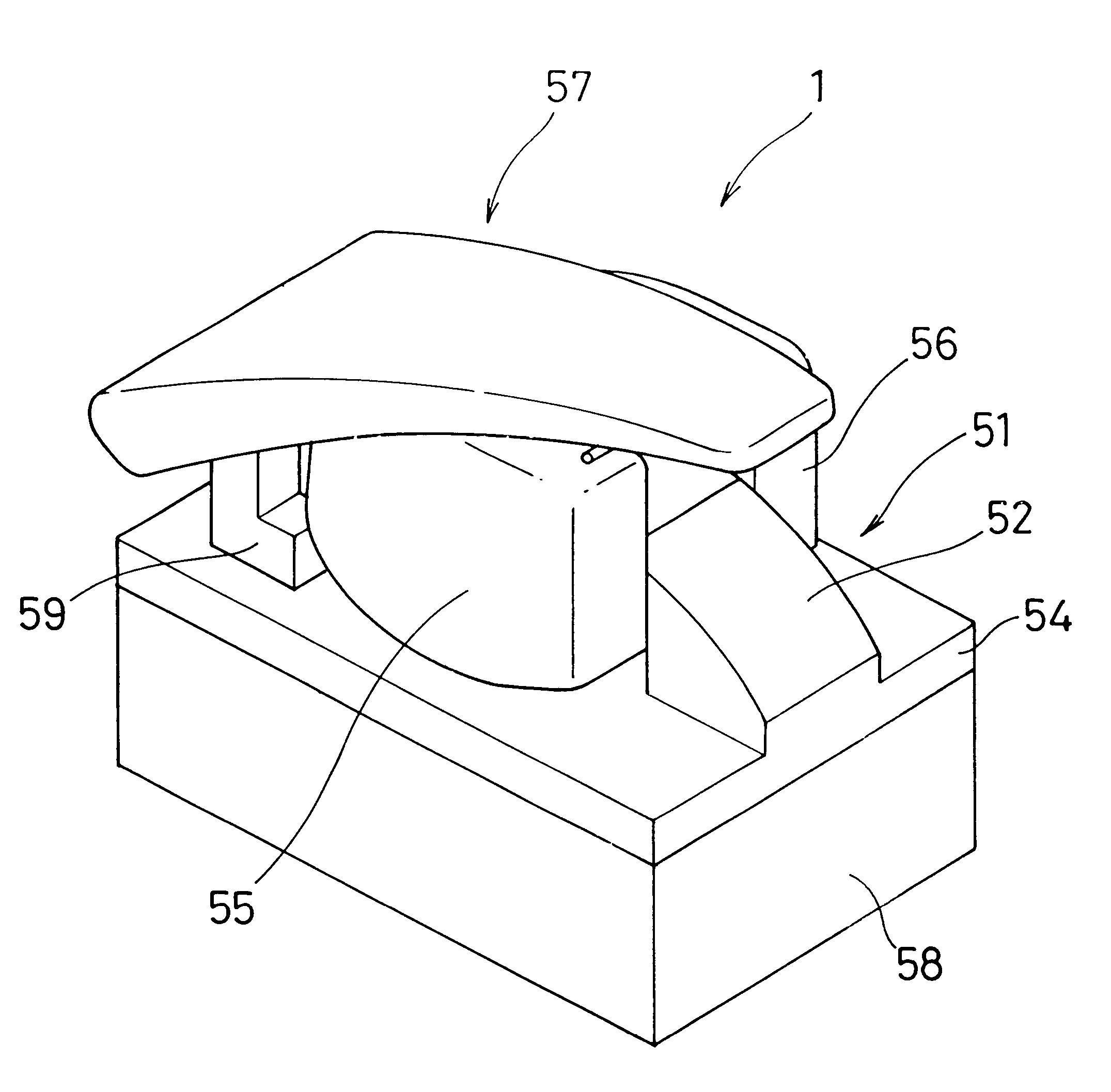
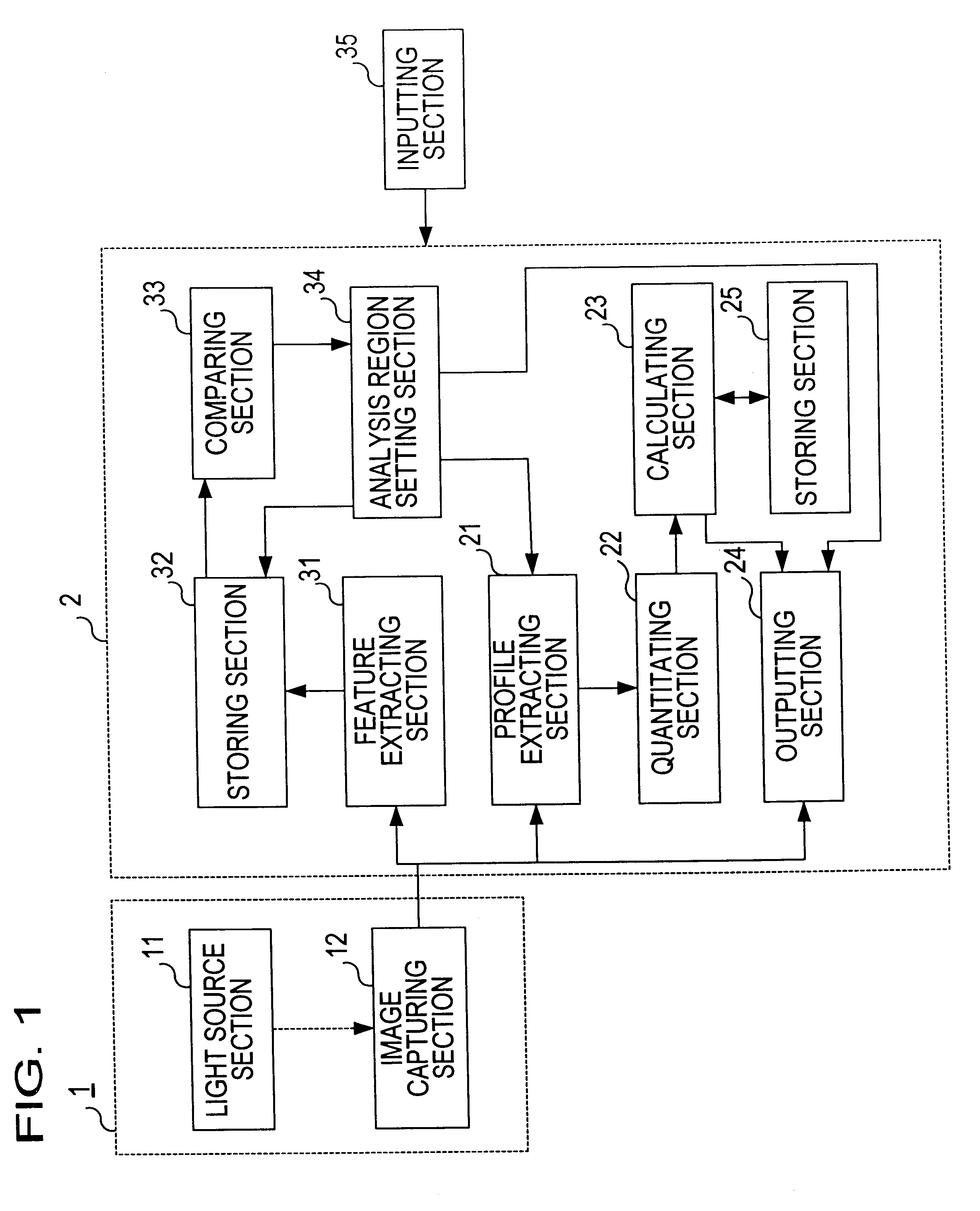
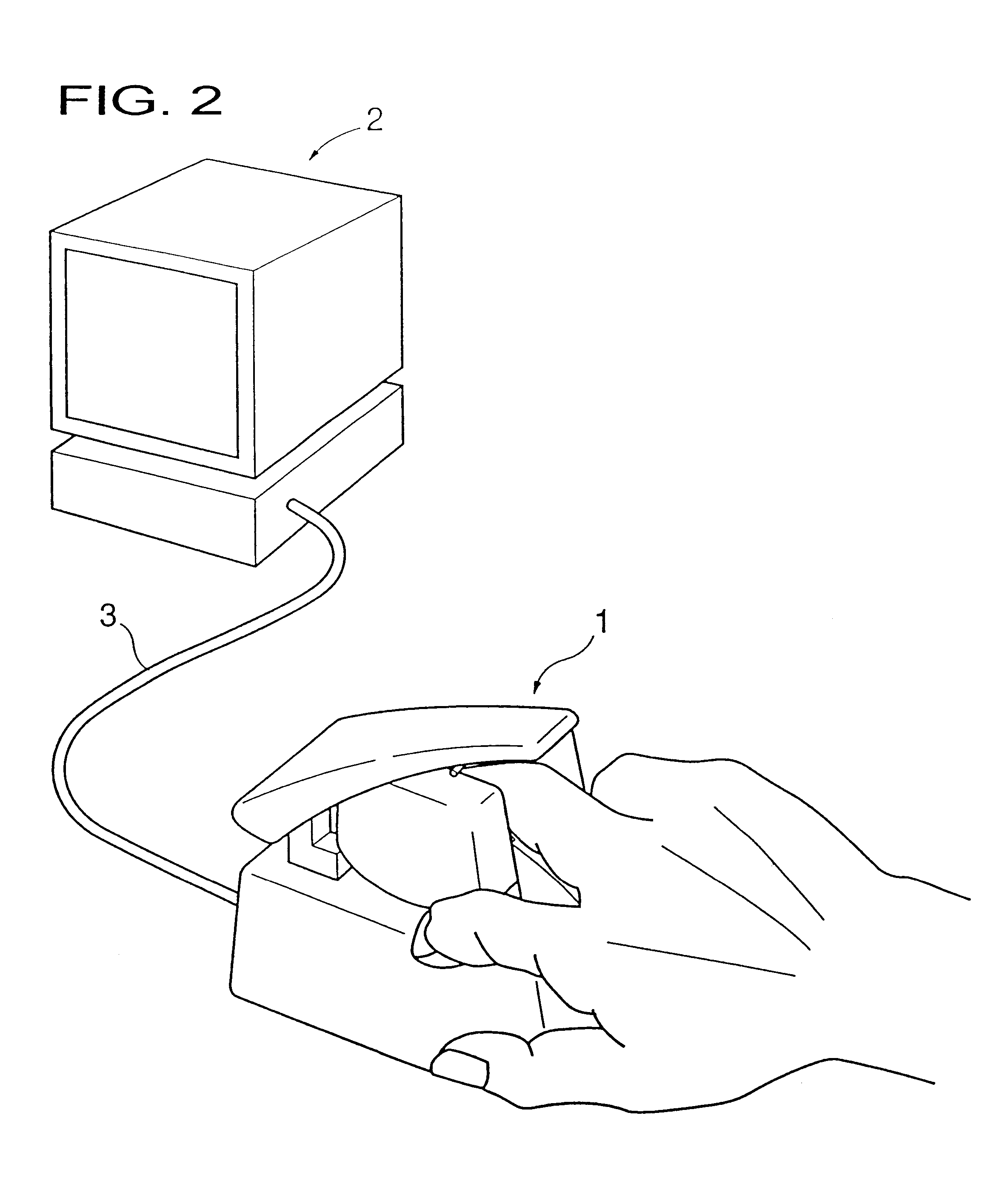
FIG. 1 is a block diagram showing a construction of a non-invasive blood analyzer employing an apparatus for living body inspection of the present invention. Referring to FIG. 1, a detecting section 1 serving as the apparatus for living body inspection is provided with a light source section 11 for irradiating a portion of the living body (a middle finger of a hand of a human being in this case) including a blood vessel and an image capturing section 12 for capturing an optical image (image of transmitted light in this case) of the irradiated portion of the living body. In other words, the detecting section 1 in this case is an apparatus for capturing an image of the living body.

An analyzing section 2 is provided with a feature extracting section 31 for extracting a positional feature of a portion of the living body (coordinates of a recess in an outline of a joint portion of a finger in this case) in each captured image when the image capturing section 12 captures an image of the p...

second embodiment

FIG. 21 is a perspective view showing a detecting section 101 according to a second embodiment of the present invention. In this embodiment, the construction of the detecting section 1 of the first embodiment has been modified and the other constructions are substantially the same as in the first embodiment.

FIGS. 22 to 27 are a left side view, a plan view, a front view, a rear view, a bottom view, and a longitudinal cross-sectional view, respectively showing the detecting section 101. Here, a right side view is symmetrical to the left side view, so that the right side view is not shown here.

FIG. 28 is a side view showing the detecting section 101 with an essential portion exposed. FIG. 29 is a crosssectional view taken along the line W--W of FIG. 28. FIGS. 30 and 31 are explanatory views showing an operation of the essential portion.

This embodiment is designed such that the whole hand (the palm, the thumb, and the fingers of the hand) can be stably mounted and measured without strai...

third embodiment

FIG. 32 is a block diagram showing a construction of a third embodiment of a detecting section and an analyzing section of the present invention. Referring to FIG. 32, the analyzing section 2a includes a judging section 26 and a light quantity controlling section 27 in addition to the elements in the analyzing section 2 (FIG. 1) of the first embodiment. Besides the added elements, like numerals denote like elements shown in FIG. 1.

In the case where a finger (middle finger) of a human hand is an object of detection as a part of a living body in the same manner as in the first and second embodiments, it is preferable that the analysis region R1 (FIG. 14) is set at a joint portion or its neighborhood because, at the joint portion, a blood vessel is present near the surface of the skin and it is easy to capture an image.

For that purpose, in this embodiment, a preliminary step is conducted before carrying out the measurement work (FIG. 12) of the first or second embodiment. Namely, the j...


PUM


Abstract

The purpose is to fix a portion of a living body, which is an object of measurement, stably without strain and to acquire accurate inspection results with good reproducibility. An apparatus for capturing an image of a living body includes: a base for mounting a portion of a living body to be inspected; two sidewall members capable of holding the mounted portion of the living body therebetween from both sides; a light source section for supplying a light to the portion of the living body held on the base and between the sidewall members; and a light receiving section for detecting optical information from the portion of the living body supplied with the light, and a non-invasive apparatus for living body inspection including the above apparatus for capturing an image of a living body in which the light receiving section includes an image capturing element, and an analyzing section for calculating information on blood flowing through a blood vessel by analyzing an image of a tissue including the blood vessel obtained by the image capturing element.

Description

1. Field of the InventionThe present invention relates to an apparatus for living body inspection and a non-invasive blood analyzer using the same, and particularly to an apparatus for transcutaneously detecting optical information from a tissue including a blood vessel of a portion of a living body and an apparatus for analyzing the detected optical information to acquire information on blood, for example, hemoglobin concentration or hematocrit.2. Description of the Related ArtFor such an apparatus for living body inspection, an apparatus is known in which a human finger is inserted into a groove of a finger accepting device, the finger is deformed by pressing it with a roller until the outline of the finger is fitted to a cross-sectional shape of the groove, and the deformed finger is irradiated with light to detect a transmitted light therefrom (for example, see Japanese Unexamined Patent Publication No. HEI 06-503728).However, in such a conventional apparatus, the finger is exte...

Claims


Application Information

Patent Timeline
IPC IPC(8): A61B5/026A61B5/00H04B10/135H04B10/532
CPCA61B5/0031H04B10/532A61B5/0261
Inventor KIMURA, ROKUSABUROASANO, KAORUKUSUZAWA, HIDEOKOUCHI, YASUHIROOZAWA, TOSHIYUKI
Owner SYSMEX CORP
Why Eureka
Try Eureka