Orthodontic supporting structure

a supporting structure and orthodontic technology, applied in the field of supports, can solve the problems of imposing a heavy burden on a patient, imposing considerable mental pain and stress on the patient, and too much to say that the molars do not move at all

Inactive Publication Date: 2002-03-12
DENTSPLY SANKIN KK
View PDF4 Cites 54 Cited by
  • Summary
  • Abstract
  • Description
  • Claims
  • Application Information

AI Technical Summary

Problems solved by technology

It is, however, too much to say that the molars do not move at all.
In such cases, the orthodontic treatment involves complicated movements and techniques for correcting the arrangement of the teeth which would require an extended period of time, imposing a heavy burden on a patient.
An extraoral anchorage orthodontic appliance, however, imposes considerable mental pain and stress on the patient because wearing the extraoral anchorage appliance greatly affects his or her daily life.
In addition, the aforementioned method of relative movement orthodontic treatment is not suited for correcting the position of a single tooth.
Therefore, the treatment is difficult to perform and requires an orthodontist to have a high level of treatment skill.
If the orthodontic supporting structure is of a type in which the implant unit and the connecting unit are fixed by a screw, the screw is necessarily an extremely small one which is considerably difficult to handle in the narrow space of the oral cavity.
If a handle of a screwdriver used for turning the screw is to be directed toward a cheek, for example, it would be even more difficult to turn the screw.
As a result, the connecting unit and the implant unit are fixed more securely and, therefore, the connecting unit will not come off easily from the implant unit.

Method used


Image

  • Orthodontic supporting structure
  • Orthodontic supporting structure
  • Orthodontic supporting structure

Examples


first example

of Treatment

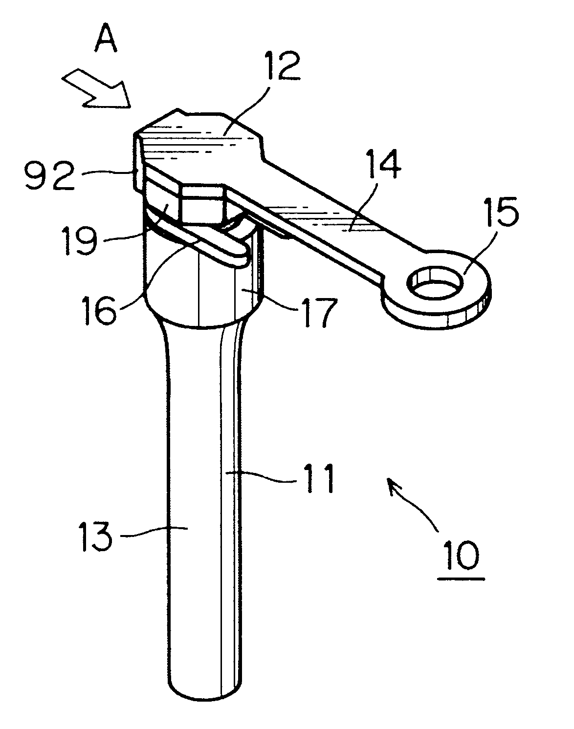
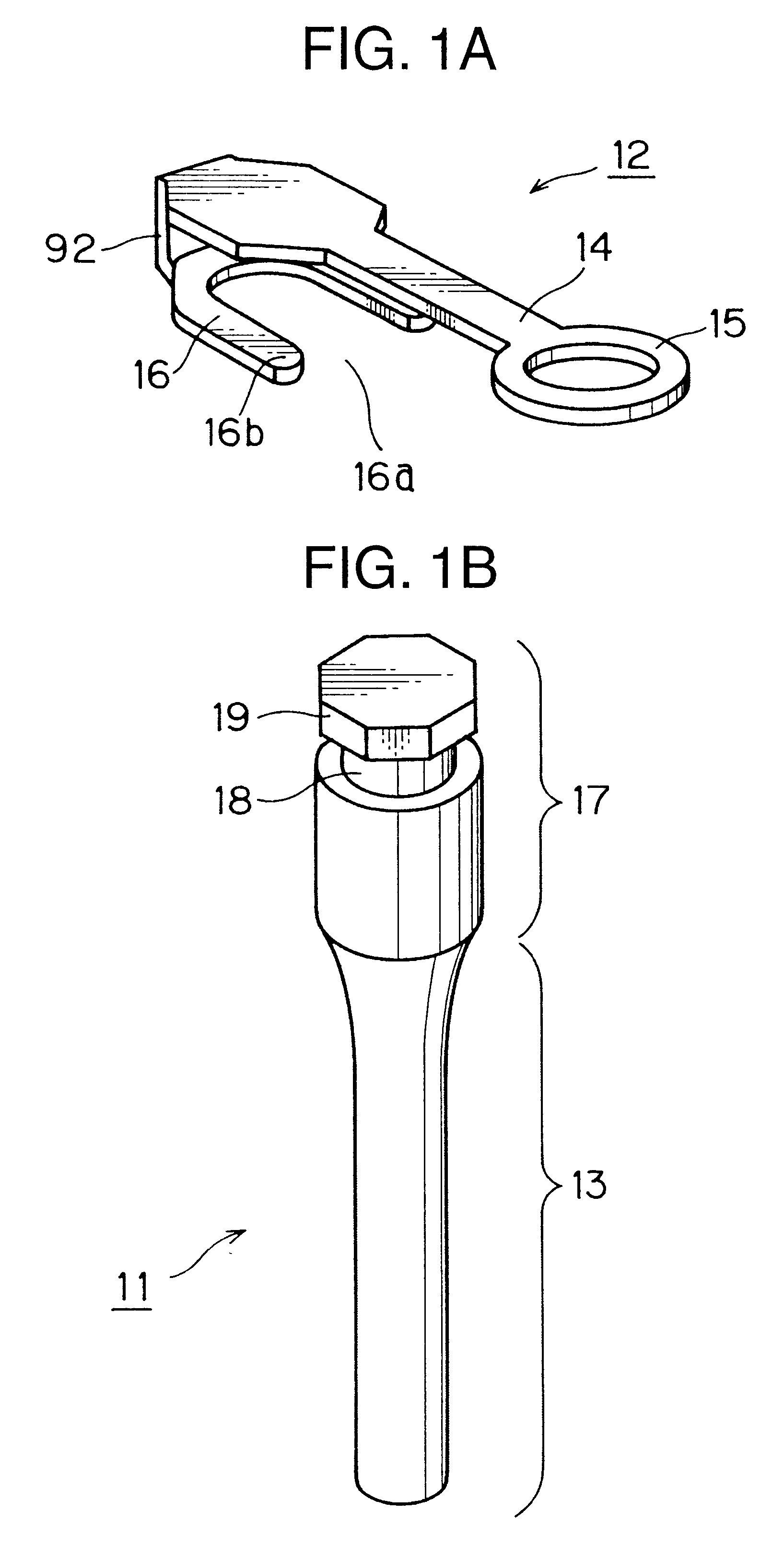
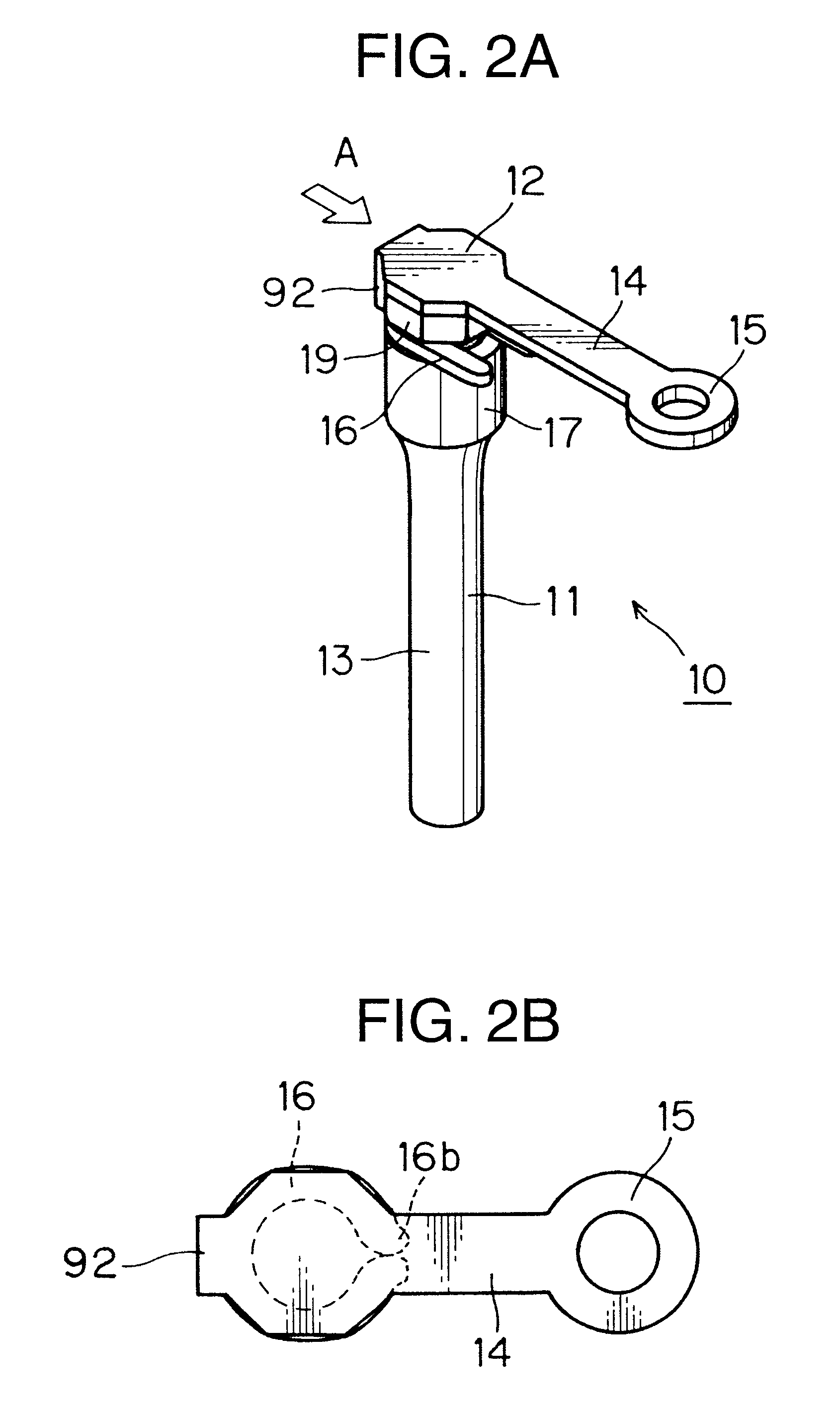
FIG. 11 is a diagram illustrating a first example of treatment according to the invention, in which the orthodontic supporting structure 30 is implanted in a jaw bone 90 which is covered with gingival mucosa 91. In FIG. 11, elements identical or equivalent to those shown in FIGS. 1A-1B, 2 and 5A-5B are designated by the same reference numerals and a description of such elements is omitted.

After implanting the implant unit 31 in the jaw bone 90, the connecting unit 12 is fixed to the implant unit 31 in the previously described manner such that the fastening part 15 is located at a desired position. Then, an orthodontist attaches one end of a wire 93 to the fastening part 15 and the other end to a bracket, for instance, which is fixed to a tooth. As a result, a correcting force is applied to the tooth from a proper direction.

According to the invention, the orthodontic supporting structure 30 is located such that its top portion is exposed to the oral cavity and a joint bet...

second example

of Treatment

FIG. 12 is a diagram illustrating a second example of treatment according to the invention, in which the orthodontic supporting structure 30 is implanted in a jaw bone 90. In FIG. 12, elements identical or equivalent to those shown in FIGS. 1A-1B, 2, 5A-5B and 11 are designated by the same reference numerals and a description of such elements is omitted.

While the arm 14 of the connecting unit 12 extends horizontally in a straight line in the example of FIG. 11, the arm 14 may be bent in an angular or curved shape as shown in FIG. 12. Such bending of the arm 14 is possible if it is made of plastically deformable material.

If a wire 93 or the like attached to the arm 14 or to the fastening part 15 goes in contact with gingival mucosa 91 and causes discomfort or inflammation, or if it is desired to slightly adjust the position of the fastening part 15 (supporting point), it may be set apart from the gingival mucosa 91 or otherwise repositioned by adjusting the bend of the ar...

third example

of Treatment

FIG. 13 is a diagram illustrating a more practical example of orthodontic treatment which is performed for lowering a canine 96.

The implant unit 31 of the orthodontic supporting structure 30 is implanted in a jaw bone 90 in such a way that the implant unit 31 would not interfere with the root or nerves of the canine 96. Subsequently, the connecting unit 12 is fixed to the implant unit 31 while holding the fastening part 15 at a position where a supporting point is to be located. Then, one end of a rubber chain 94 is attached to the fastening part 15 of the connecting unit 12 and the other end of the rubber chain 94 is fitted to a bracket 95 which is fixed to the canine 96, such that a downward pulling force is applied to the canine 96.

Fourth and Fifth Examples of Treatment

FIG. 14 is a diagram illustrating a fourth example of treatment according to the invention, in which two pairs of teeth 99 in the upper jaw are corrected using two orthodontic supporting structures. In ...


PUM


Abstract

An orthodontic supporting structure of the present invention comprises an implant unit which is implantable in a jaw bone and a connecting unit which includes an arm part having a fastening portion. The implant unit has a narrow part in its upper portion. The connecting unit further includes an engaging part having an opening at one end. The engaging part fits on the narrow part of the implant unit. The connecting unit can be attached to the implant unit in a simple way by sliding the engaging part along the narrow part and then crimping far ends of the engaging part.

Description

1. Field of the InventionThe present invention relates to supports for correcting abnormal dentition which can serve as supporting points for relocating or moving an improperly positioned tooth in orthodontic treatment.2. Description of the Related ArtOrthodontic treatment for correcting irregularities in teeth arrangement, such as crowded teeth, reversed occlusion or inclination of front teeth to the labial side, is getting popular.One of the most popular methods of orthodontic treatment includes the steps of fixing brackets to surfaces of individual teeth with an adhesive, for instance, passing an arch wire through the brackets, and relatively moving the individual teeth by applying external forces (which may be hereinafter referred to as correcting forces in this Specification), such as pushing, pulling or twisting forces, to the teeth by use of a restoring force caused by the elasticity of the arch wire, so that the teeth would be adjusted to take proper positions and directions...

Claims


Application Information

Patent Timeline
Patent Type & Authority Patents(United States)
IPC IPC(8): A61C7/00A61C8/00A61B17/56A61C7/20
CPCA61C7/00A61C8/0018A61C8/0096
Inventor KANOMI, RYUZONAKAGAWA, KATSUYUKISHIN, YOSHIHARU
Owner DENTSPLY SANKIN KK
Why Eureka
Try Eureka