Digital filters

a filter and digital technology, applied in the field of digital filters, can solve the problems of large circuit size, difficult to reduce the overall circuit size, and large circuit size, and achieve the effect of reducing the overall circuit siz

Inactive Publication Date: 2002-03-19
SEMICON COMPONENTS IND LLC
View PDF4 Cites 62 Cited by
  • Summary
  • Abstract
  • Description
  • Claims
  • Application Information

AI Technical Summary

Problems solved by technology

Because an array of delay elements 1 and multipliers 2, corresponding to the number of taps N are required, this type of digital filter has a problem that its entire circuit size becomes larger as the number of the taps increases.
Such a device enabling both sound recording and reproduction is required to have both separation and synthesis filters, which creates a problem that circuit size is made larger.
Even if the QMF based on the above-mentioned stored program method is used, two sets of multipliers and accumulators are required and it is difficult to reduce the overall circuit size.
In a digital data arithmetic processing circuit, the increase in the number of multipliers, which are relatively large circuit components, makes the arithmetic units complex, thus resulting in the increase of the cost.
Particularly, when processing the audio data consisting of a large number of bits, the increase of multipliers is liable to have a significant effect on the increase of the cost.

Method used


Image

  • Digital filters
  • Digital filters
  • Digital filters

Examples


first embodiment

[First Embodiment]

FIG. 5 is a block diagram showing a digital filter configured according to a first embodiment of the present invention.

RAM 41, connected to a second selector 54 which will be described below, stores time-series data which has been input to it from the second selector 54 for a predetermined period. Each data stored in the RAM 41 is sequentially read out for the arithmetic processing step. From a ROM 42, in which a plurality of filter coefficients h(k) have previously been stored, a step-specific filter coefficient h(k) with a value of k incrementing step by step is read out repeatedly, where k corresponds to the k given in the above-mentioned equations (9) through (12). A multiplier 43, connected to the RAM 41 and the ROM 42, multiplies the data read from the RAM 41 by the filter coefficient h(k) read from the ROM 42. An accumulator 44 consisting of an adder 45 and a register 46 is connected to the multiplier 43. The accumulator 44 accumulates the product of each mu...

second embodiment

[Second Embodiment]

FIG. 8 is a block diagram showing a digital filter configured in accordance with a second embodiment of the present invention.

A digital filter according to the second embodiment allows the parallel input of data Xa(n) and Xb(n) when operating as the synthesis filter. In the second embodiment, a pair of selectors 47a and 47b arranged in parallel replace the first selector 47 of the digital filter shown in FIG. 5. These selectors are designed to operate as follows. One selector 47a selects either the accumulation data supplied from the accumulator 44 or the input data Xa(n) and supplies the selected data to the first register 48. The other selector 47b selects the accumulation data supplied from the accumulator 44 or the input data Xb(n) and supplies the selected data to the second register 49. With the exception of a pair of the registers 47a and 47b, the structure and operation of the digital filter in the second embodiment corresponds to that in the first embodim...

third embodiment

[Third Embodiment]

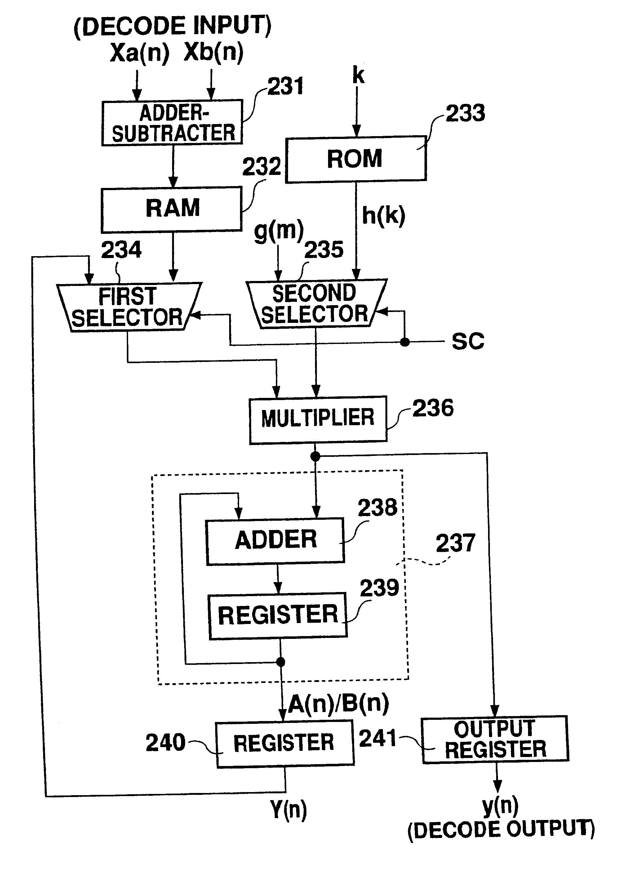
FIG. 9 is a block diagram showing a digital filter configured in accordance with a third embodiment of the present invention.

A RAM 131, connected to a multiplier 135 which is explained below, stores for a given period the attenuated input data x(n) which has been input to it from the multiplier 135. Each data stored in the RAM 131 is sequentially read and output to the multiplier 135 when subjected to a further arithmetic processing step. From a ROM 132, in which a plurality of filter coefficients h(k) have previously been stored, a step-specific filter coefficient h(k) with a value of k incrementing step by step is read out repeatedly, where k corresponds to the k given in the above-mentioned equations (9) and (10). A first selector 133, connected to the encode input and the RAM 131, selects and outputs either time-series input data X(n) or the attenuated input data x(n) read from the RAM 131. A second selector 134, connected to the attenuation input and the ROM 3...


PUM


Abstract

A digital filter is provided with a plurality of selectors. Switchover from one selector to another switches the digital filter operation between a separation filter function and a synthesis filter function. When the digital filter functions as either separation filter or synthesis filter, it switches over between the functions of multiplying data by a filter coefficient and multiplying data by an attenuation coefficient. The entire digital filter circuit size can thus be reduced.

Description

1. Field of the InventionThe present invention relates to digital filters that are used for digital audio devices in order to execute digital data separation and / or synthesis.2. Description of the Related ArtA Finite Impulse Response (FIR) type digital filter is constructed so that output data Y(n) will be produced by convoluting input data X(n) and impulse responses, as expressed by equation (1). ##EQU1##where, h(k) is a filter coefficient and N is the number of taps. When transformed with regard to Z, the equation (1) will be as follows: ##EQU2##The equation (2) will be further transformed as follows: ##EQU3##The equation (3) determines a frequency response. Assuming that .omega.=2.pi.k / N, the equation (3) will be as follows: ##EQU4##This equation (4) may be regarded as an expression of Discrete Fourier Transformation (DFT). Thus, the filter coefficient h(k) is obtained through Inverse Discrete Fourier Transformation (IDFT) of the frequency characteristic given by the equation 4.F...

Claims


Application Information

Patent Timeline
Patent Type & Authority Patents(United States)
IPC IPC(8): H03H17/02
CPCH03H17/0294H03H17/02
Inventor TAKANO, KOJINAGAO, FUMIAKI
Owner SEMICON COMPONENTS IND LLC
Why Eureka
Try Eureka