
Control of flow separation with harmonic forcing and induced separation

a flow separation and harmonic technology, applied in the direction of engine components, circuit elements, thin material processing, etc., can solve the problems of endangering the effectiveness of the control, difficult to correctly position the control device, and point to migrate a functionally significant distance, so as to reduce the parasitic drag and energy consumption.

Inactive Publication Date: 2002-03-26
RAYTHEON TECH CORP
View PDF6 Cites 21 Cited by
  • Summary
  • Abstract
  • Description
  • Claims
  • Application Information

AI Technical Summary

Benefits of technology

Objects of the present invention include provision of a flow boundary layer separation control with smaller parasitic drag, and requiring less energy than prior forcing techniques.

Problems solved by technology

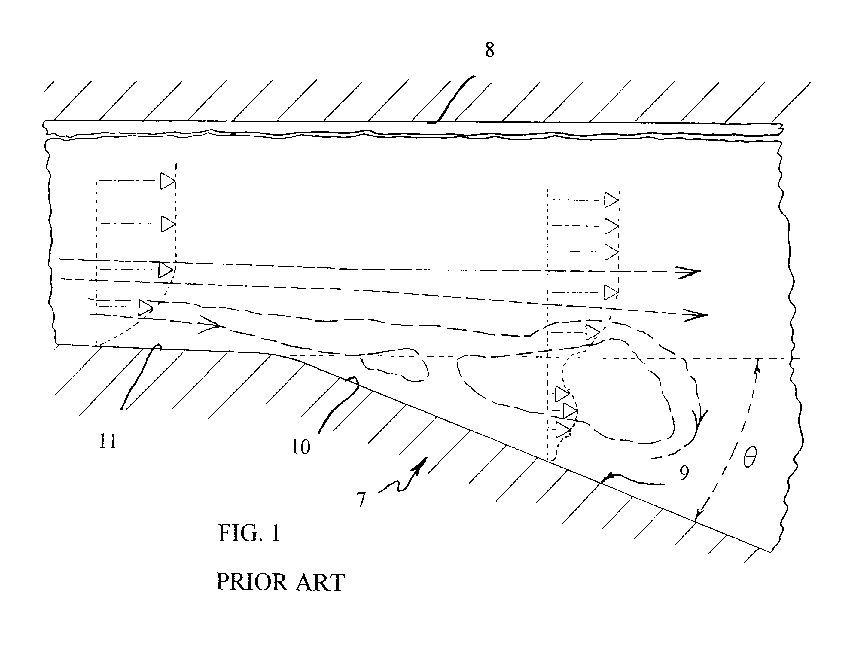
This invention is predicated partially on the realization that the unsteady nature of flow structures in and near a boundary layer result in motion of the separation point in an uncontrolled flow, whereby a point of receptivity to a control impetus is not well defined, nor static, which makes it difficult to position the control device correctly and thereby endangers the effectiveness of the control when any change in flow conditions may cause the separation point to migrate a functionally significant distance from the control location.

Method used


Image

  • Control of flow separation with harmonic forcing and induced separation
  • Control of flow separation with harmonic forcing and induced separation
  • Control of flow separation with harmonic forcing and induced separation

Examples


Embodiment Construction

Referring to FIG. 1, a two-dimensional expansion 7 has an upper surface 8 parallel with the flow and a lower surface 9 with an expanding wall 10 at an included angle, .theta., of about 23.degree., and a parallel wall 11. The flow, indicated by dash lines, reveals large transitory stall, involving large-scale, unsteady separation. In FIG. 1, the dot / dash arrows and the dotted lines indicate magnitude of flow velocity, but not direction.

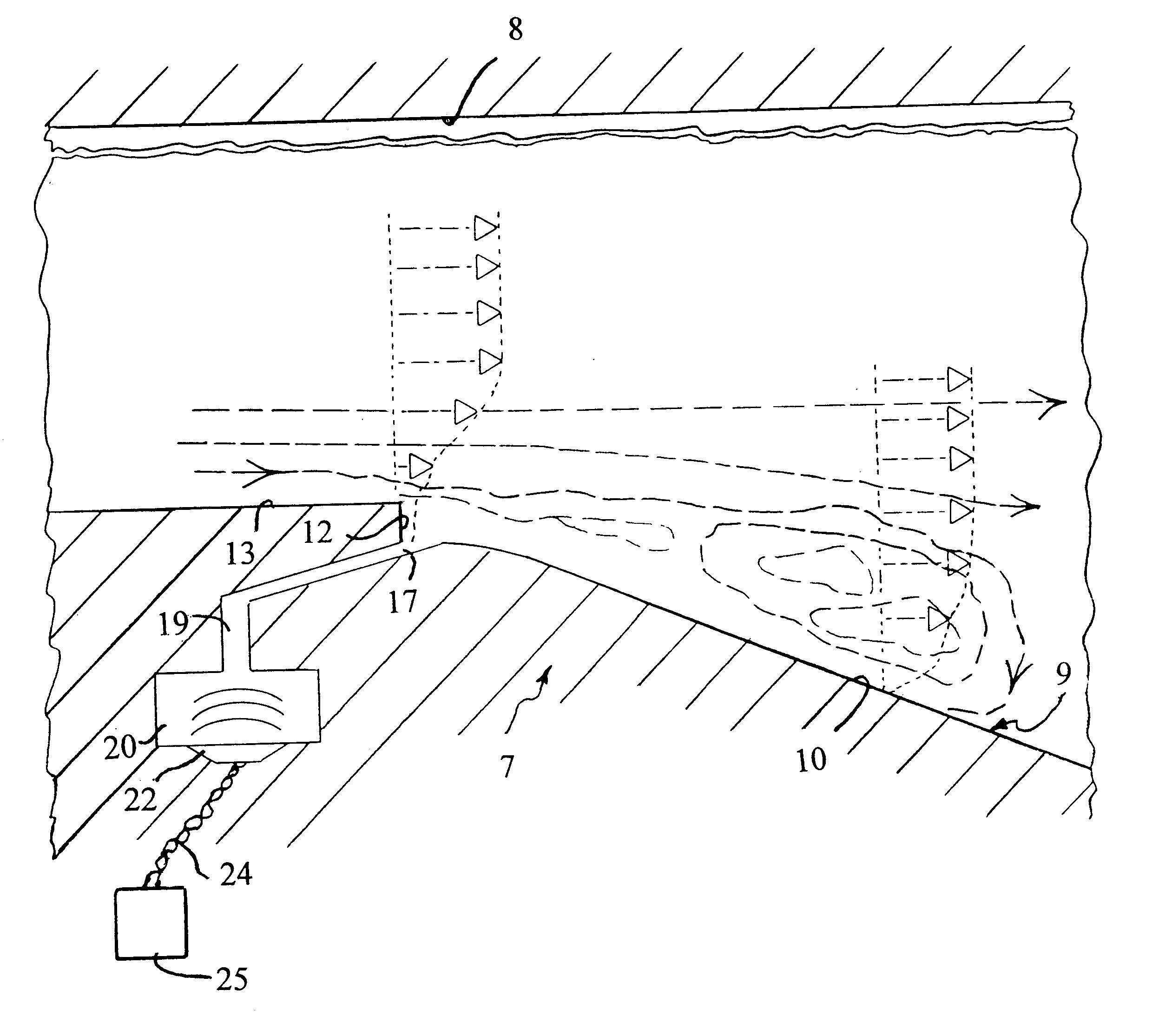
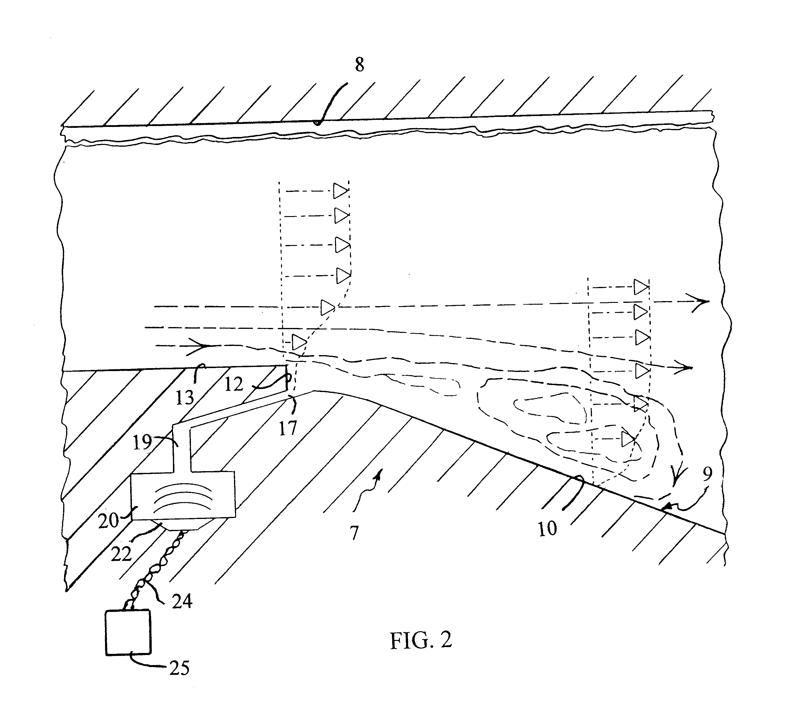
Referring to FIG. 2, in accordance with the invention, the expander surface 9 is provided a protrusion formed by a reverse step 12 between a surface 13 which is parallel to the inlet flow, and the diffuser surface 10 induces a small-scale flow separation, somewhat greater than the thickness of the boundary. At the base of the step 12 there is an inlet 17, which comprises a cross stream slot connected by means of a channel 19 to a chamber 20 to which there is attached a loudspeaker 22, to obtain an oscillatory, zero-mass flux fluid flow into and out of ...


PUM


Abstract

A diffuser (7) has a step (12) in the surface (9) just upstream of a point where boundary layer separation might occur. An acoustic jet (22) has a nozzle (17) immediately downstream of the step (12); the acoustic jet is driven (25) by a plurality of frequencies, one or more of which are subharmonics of another of them, and having different phases.

Description

This invention relates to controlling the separation of boundary layer flow by means of the combination of a small protrusion just upstream of the expected separation point and dynamic forcing, through a slot at the downstream base of the protrusion, in response to harmonically and phase related forcing signals.Loss of efficiency and performance as a consequence of boundary layer flow separation is known to cause retreating blade stall, drag of bluff bodies, jet engine air inlet distortion, as well as losses in diffusers, heat exchangers and pumps in heating, ventilating and air conditioning systems. Known separation controls have included passive vortex generators as well as blowing or suction in the near-wall regions where separation may occur. A recent approach that causes the boundary layer to absolutely attach to the surface is disclosed in commonly owned U.S. patent application Ser. No. 09 / 257,565, filed on Feb. 25, 1999, which achieves clearly superior results with significan...

Claims


Application Information

Patent Timeline
Patent Type & Authority Patents(United States)
IPC IPC(8): F15D1/06F15D1/00
CPCF15D1/06F15D1/003F05B2260/962Y10T137/2196Y10T137/2224Y10T137/0391Y10T137/2185
Inventor NARAYANAN, SATISHNOACK, BERND R.BANASZUK, ANDRZEJKHIBNIK, ALEXANDER I.
Owner RAYTHEON TECH CORP
Learn More