
Temperature controlled compensated oscillator

a compensation oscillator and temperature control technology, applied in the direction of oscillator stabilization, electrical equipment, oscillator generators, etc., can solve the problems of high cost of sc cut crystals, difficult manufacture of tcxos with specifications approaching 0.1 ppm, and inconvenient use of tcxos

Inactive Publication Date: 2002-03-26
CTS CORP ELKHART
View PDF7 Cites 51 Cited by
  • Summary
  • Abstract
  • Description
  • Claims
  • Application Information

AI Technical Summary

Benefits of technology

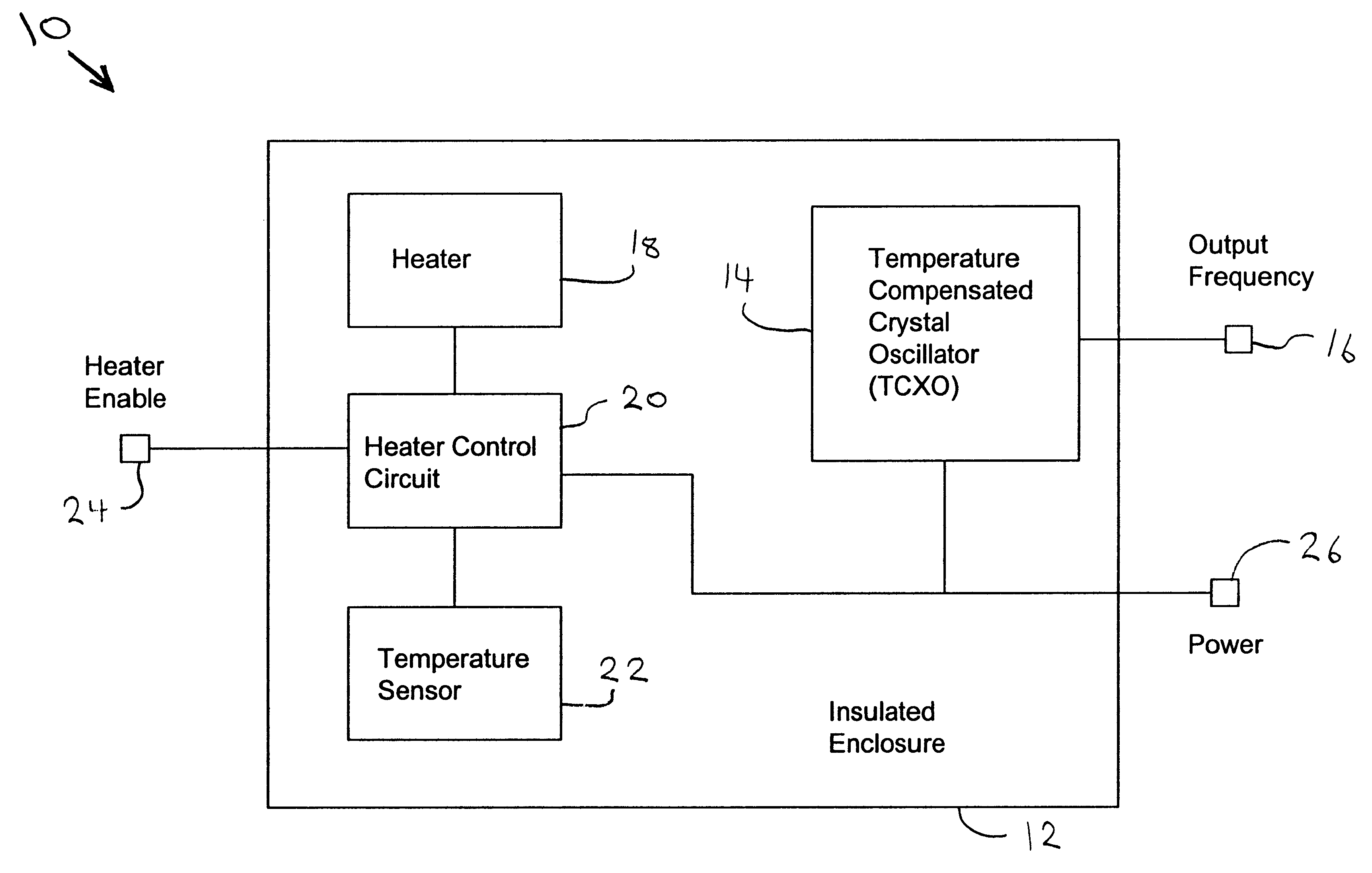
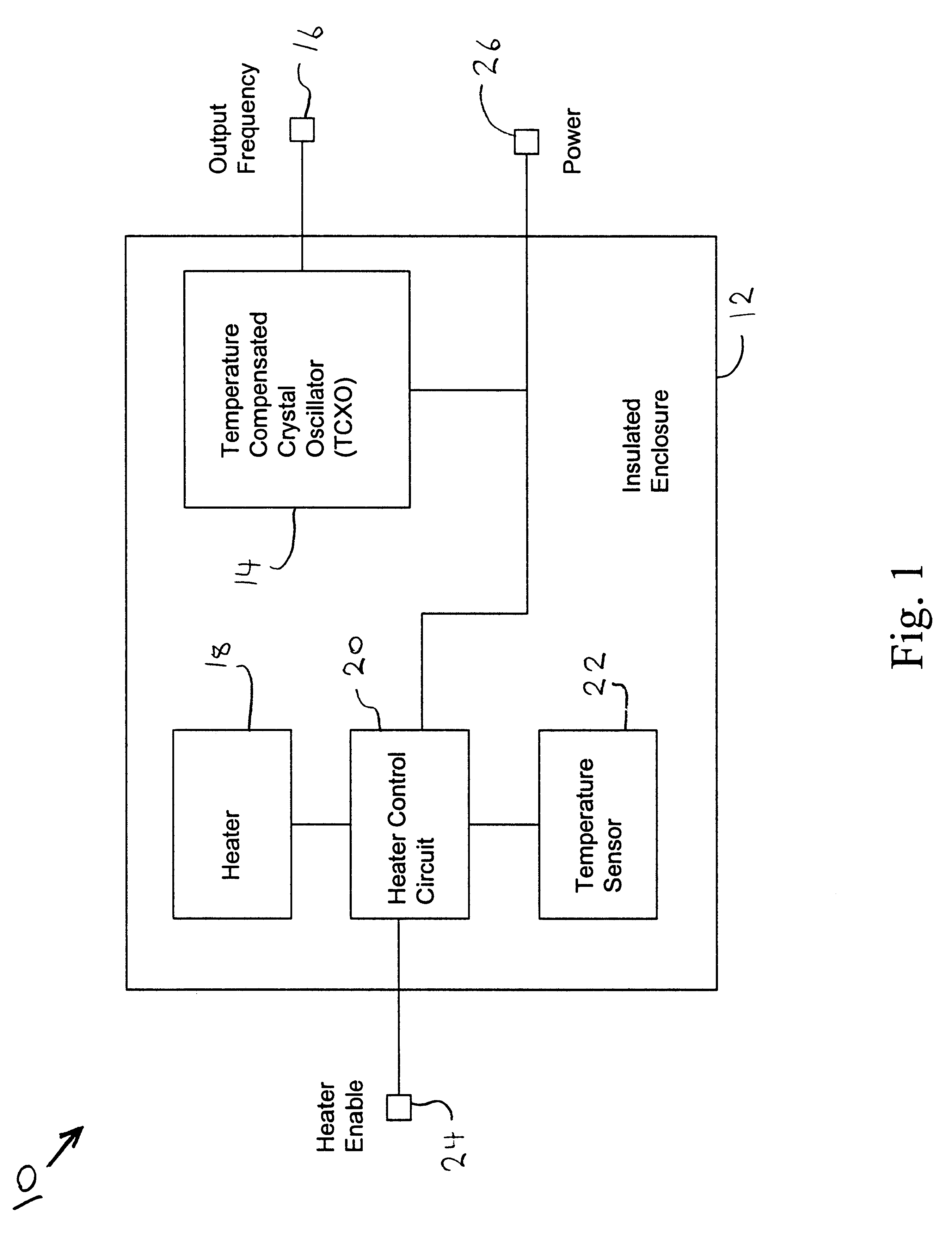
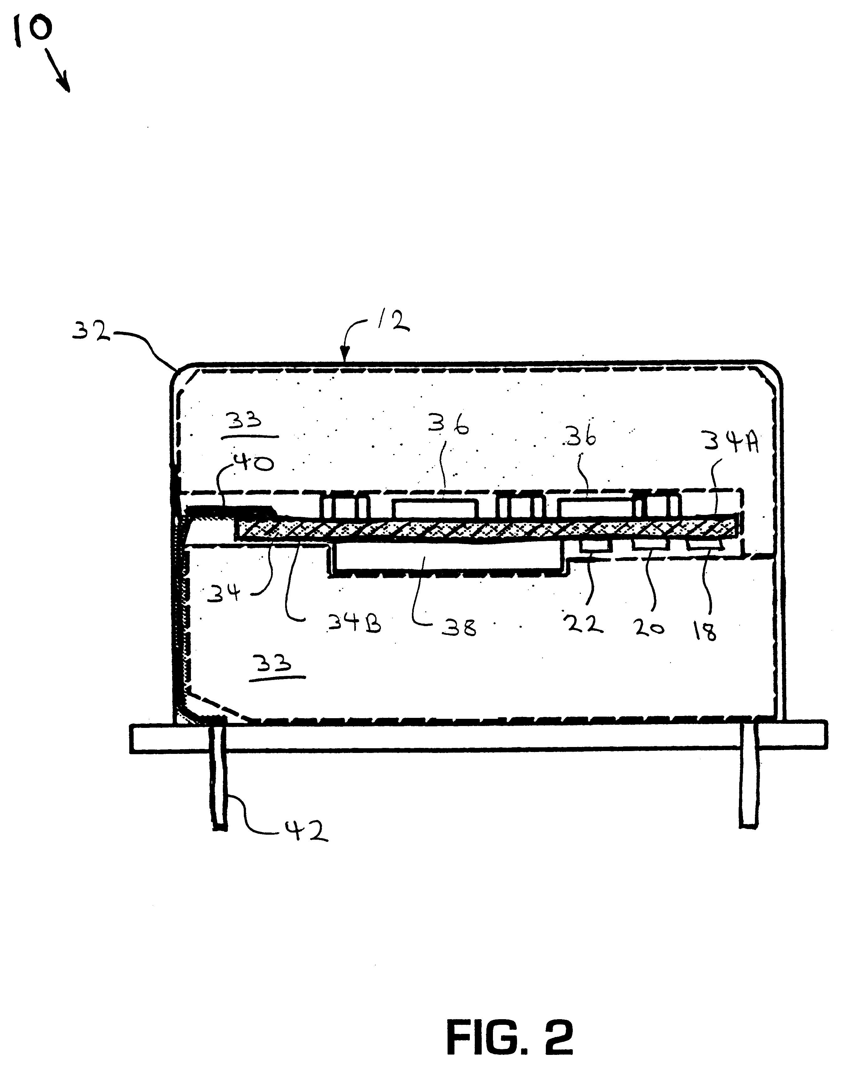
A further feature of the invention is to provide an oscillator assembly that includes a substrate and a temperature compensated crystal oscillator mounted on the substrate for producing a reference frequency. A temperature controller is mounted on the substrate. The substrate is located in a housing. The temperature controller provides a stable temperature to the temperature compensated crystal oscillator such that deviations from the reference frequency are reduced.

Problems solved by technology

This hysterisis makes the manufacture of TCXOs with specifications approaching 0.1 PPM quite difficult.
The high precision crystals found in oven oscillators exhibit less retrace but they are unsuitable for use in TCXOs because they often exhibit activity dips at temperatures below the designed oven temperature and SC-cuts and high overtone types cannot be tuned by a sufficient amount to compensate for the frequency excursion.
In addition SC cut crystals are very expensive.
Ovenized oscillators allow the use of SC-cut crystals which offer superior characteristics but which are impractical for ordinary TCXOs because of their steep frequency drop at cooler temperatures.
Unfortunately SC cut crystals are much more expensive to produce than AT cut crystals typically used in TCXO's.
Oven oscillators have a higher power consumption than temperature compensated oscillators.
SC-cut crystals stabilize as soon as they reach the operating temperature but AT-cut crystals exhibit a significant thermal transient effect which can take many minutes to settle.
This cooling transient can kick the AT-cut in the other direction and may actually result in a shorter warm-up time even though the controller takes longer to settle.
Hand tweaked designs can achieve fairly good warm-up times with carefully selected overshoot but the advent of quick settling SC-cut crystals obsoleted this approach.
Despite the advantages of the prior art oscillators, an unmet need exists for an oscillator that has the high performance of an ovenized oscillator at the low cost of a temperature controlled crystal oscillator.

Method used


Image

  • Temperature controlled compensated oscillator
  • Temperature controlled compensated oscillator
  • Temperature controlled compensated oscillator

Examples


Embodiment Construction

(S)

1. Field of the Preferred Embodiment(s)

This invention relates to oscillators which provide a stable reference frequency signal in computers or other electronic equipment. Specifically, there is a temperature compensated crystal oscillator that is contained within an ovenized enclosure to increase the stability of the reference frequency signal.

2. Description of the Related Art

Various devices are well known for providing a reference frequency or source such devices are called oscillators. The oscillator typically has a quartz crystal or other resonator and also has electronic compensation circuitry to stabilize the output frequency.

Various methods are known to stabilize the output frequency as the temperature of the oscillator changes. Temperature compensated crystal oscillators (TCXO's) typically employ a thermistor network to generate a correction voltage which reduces the frequency variation over temperature. The correction voltage is usually applied to a varactor diode in the ...


PUM


Abstract

A temperature compensated crystal oscillator using an AT cut crystal produces a reference frequency. The temperature compensated crystal oscillator is located inside a temperature controlled oven. The temperature controlled oven provides a stable temperature to the temperature compensated crystal oscillator such that deviations from the reference frequency are reduced.

Description

BACKGROUND OF THE PREFERRED EMBODIMENT(S)1. Field of the Preferred Embodiment(s)This invention relates to oscillators which provide a stable reference frequency signal in computers or other electronic equipment. Specifically, there is a temperature compensated crystal oscillator that is contained within an ovenized enclosure to increase the stability of the reference frequency signal.2. Description of the Related ArtVarious devices are well known for providing a reference frequency or source such devices are called oscillators. The oscillator typically has a quartz crystal or other resonator and also has electronic compensation circuitry to stabilize the output frequency.Various methods are known to stabilize the output frequency as the temperature of the oscillator changes. Temperature compensated crystal oscillators (TCXO's) typically employ a thermistor network to generate a correction voltage which reduces the frequency variation over temperature. The correction voltage is usual...

Claims


Application Information

Patent Timeline
IPC IPC(8): H03L1/02H03L1/04H03L1/00H03B5/04
CPCH03B5/04H03L1/022H03L1/04H03L1/023H03L1/028
Inventor FRY, STEVEN J.
Owner CTS CORP ELKHART
Learn More