
Fail-safe illuminated display comprising multimodal illumination components

a multi-modal illumination and display technology, applied in the field of illuminated displays, can solve the problems of ineffective without incident light, fluorescent dyes, and all active illuminated displays of the prior art suffer the significant deficiency of becoming unreadable in low or no ambient light conditions

Inactive Publication Date: 2002-04-02
ASTRONICS
View PDF11 Cites 49 Cited by
  • Summary
  • Abstract
  • Description
  • Claims
  • Application Information

AI Technical Summary

Benefits of technology

will be more fully appreciated with reference

Problems solved by technology

Fluorescent dyes and pigments are commonly used to alter color and enhance contrast in such applications, but are ineffective without incident light.
All actively illuminated displays of the prior art suffer the significant deficiency that they become unreadable in low or no ambient light conditions, e.g., upon a failure or interruption of power delivery to the display.
In critical applications, such as instrumentation in aircraft and other vehicles, or signs demarcating emergency exits, a backup power source for illumination must be provided, increasing the cost, complexity, and labor requirements (inspection, testing and maintenance) of the overall system.
In addition to failure from loss or interruption of power, all actively illuminated displays suffer the deficiency of loss of readability through failure of one or more of the active illumination elements (such as incandescent bulbs, LEDs, fluorescent tubes, etc.) or their associated circuitry components.
These displays may be designed to include various redundancies to increase their reliability, but this also increases cost, complexity, and maintenance requirements of the overall system.

Method used


Image

  • Fail-safe illuminated display comprising multimodal illumination components
  • Fail-safe illuminated display comprising multimodal illumination components
  • Fail-safe illuminated display comprising multimodal illumination components

Examples


Embodiment Construction

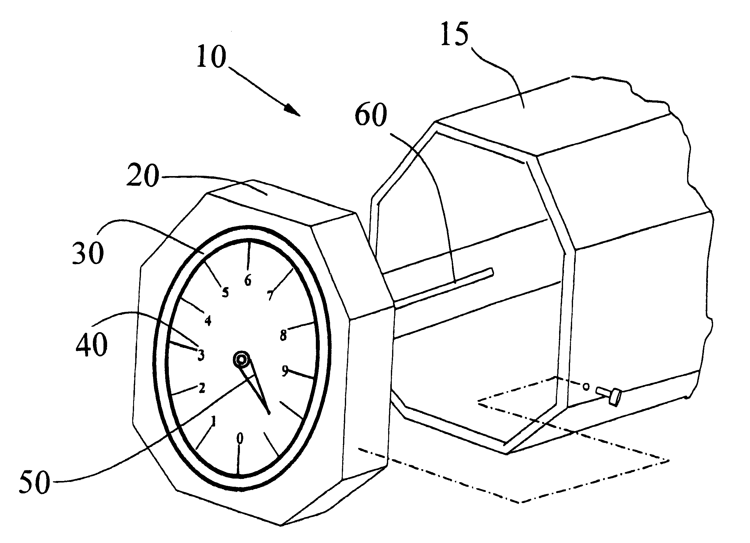
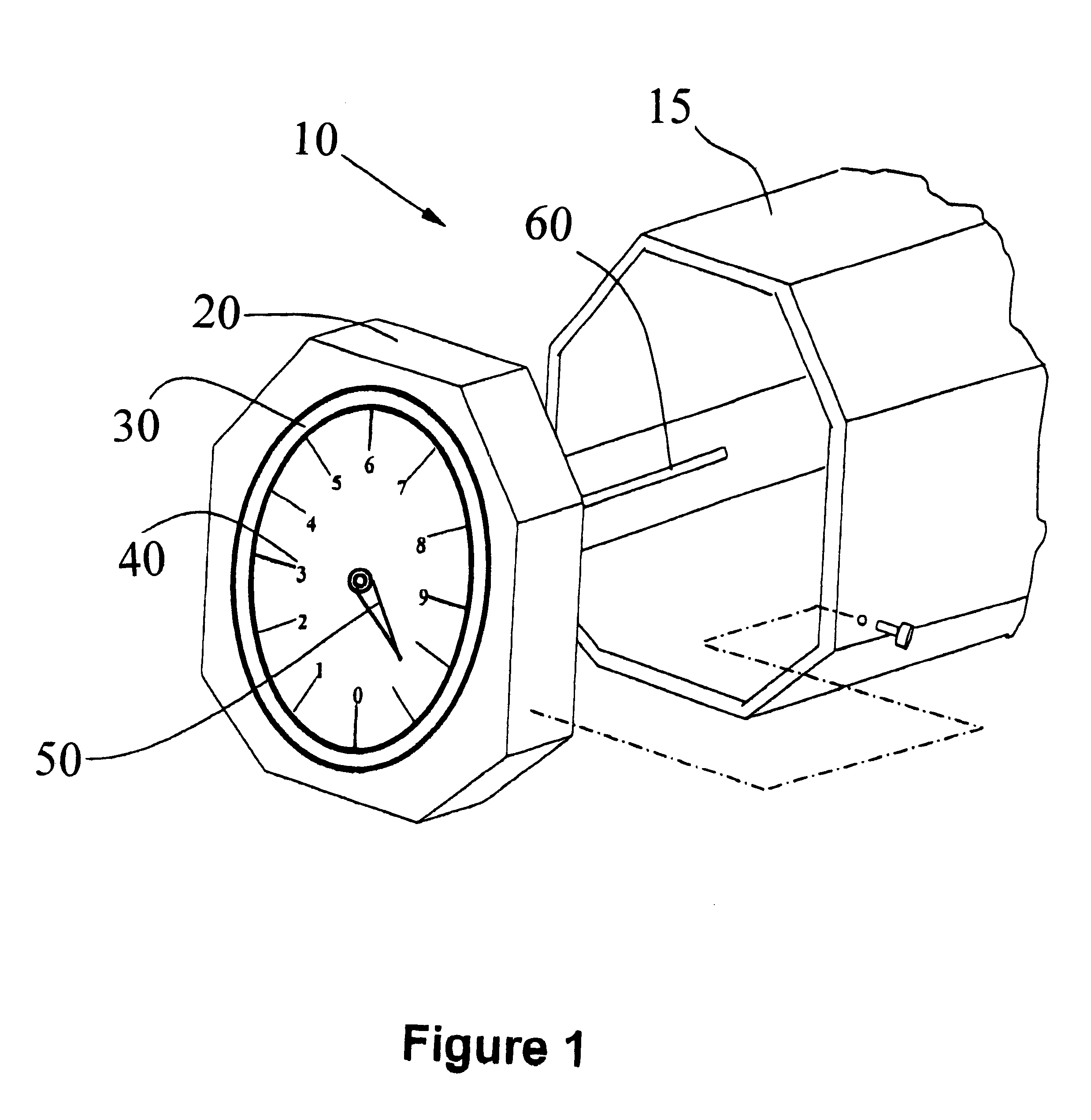
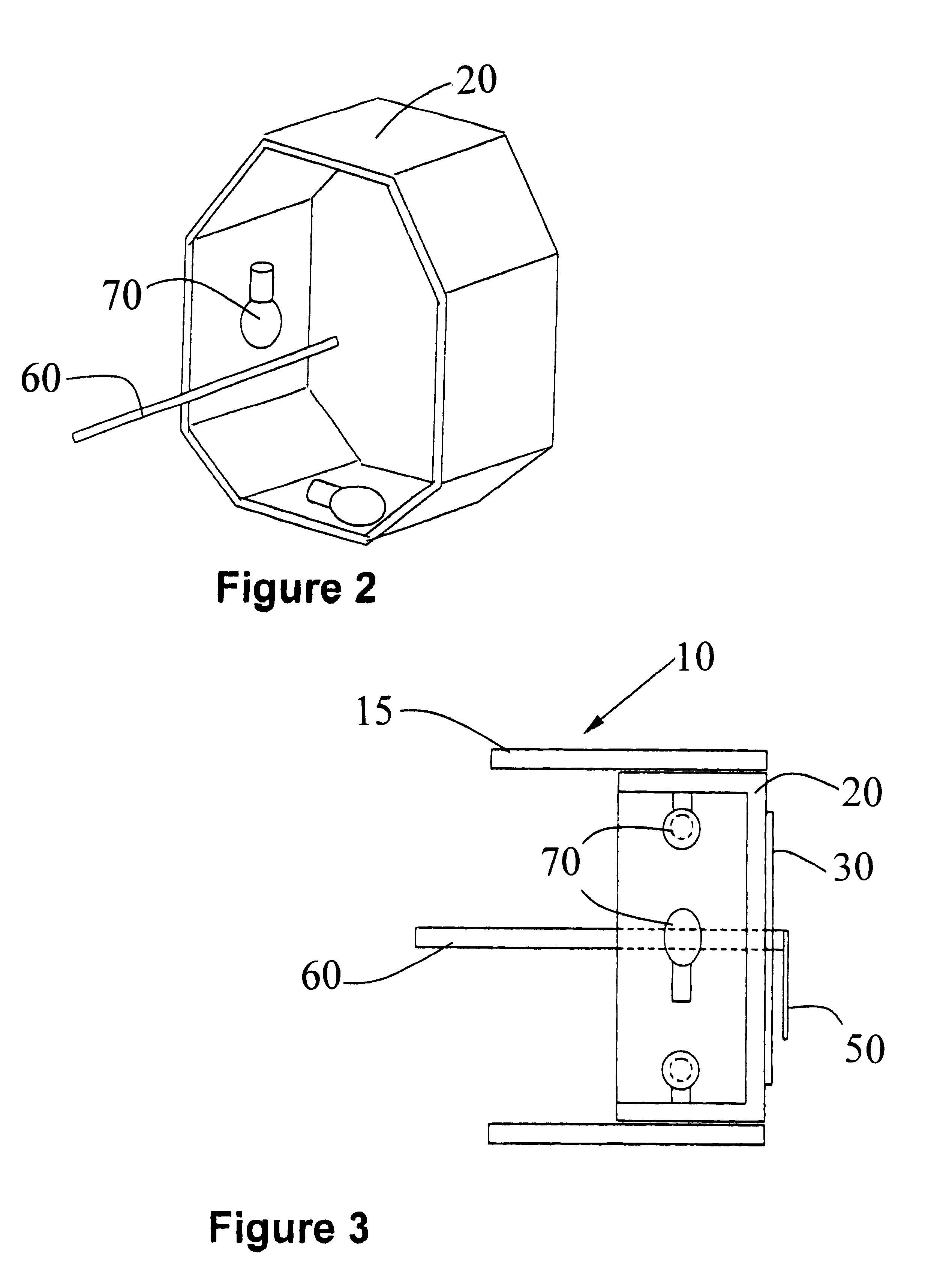
The present invention generally relates to lighted display, e.g., for signage or other visual communication, comprising multimodal illumination components arranged for illuminative operation even during temporal loss of power to the display.

More particularly, the present invention relates to a display utilizing conventional powered lighting means, and photoluminescent pigment which is charged by daylight or the powered lighting means, and provide passive illumination in the event of loss of power. The photoluminescent material stores optical energy when exposed to ambient light, and slowly radiates optical energy long after the redution or removal of the ambient light. Typically, photoluminescent materials absorb energy in the UV to blue range and re-emit energy in the blue to red and near IR range. The passive illumination capability of the display may further be augmented by the provision of fluorescent material provided in light-receiving relationship to the photoluminescent mate...


PUM


Abstract

An illuminated display that is susceptible to interruption or termination of active lighting capability and provides passive lighting capability in such circumstances. The illuminated display features an active illumination source providing active lighting capability and a display member (i) arranged in light-receiving relationship to the active illumination source and (ii) containing photoluminescent pigment incorporated therein in sufficient amount and distribution to illuminate the display during the interruption or termination of active lighting capability, to provide passive lighting capability. The illuminated display may further include a fluorescent pigment arranged in photoluminescent light-receiving relationship to the display member containing the photoluminescent pigment, whereby the fluorescent pigment down-converts photoluminescent light from the display member during the interruption or termination of active lighting capability.

Description

1. Field of InventionThe present invention generally relates to a lighted display, e.g., for signage or other visual communication, comprising multimodal illumination components arranged for illuminative operation even during temporal loss of power to the display.2. Brief Description of the Related ArtMany forms of visual displays must be readily visible under a wide variety of lighting conditions. As discussed herein, the term "display" is to be understood as broadly including informational, pictorial or graphic displays, e.g., containing alphabetic and / or numeric text, graphic components, icons, symbols or other visually discernable indicia. Specific examples include: signage such as scoreboards, schedule displays in airport terminals, bus stations, train stations, and stadiums; instrument displays, such as those found in the instrument panels of aircraft cockpits, automobiles, and in other vehicles; and display panels on industrial and office equipment, appliances, telephones, nu...

Claims


Application Information

Patent Timeline
IPC IPC(8): G09F13/20
CPCG09F13/20G08B7/062
Inventor BURBANK, ROBERT M.
Owner ASTRONICS
Learn More