Light emitting device with phosphor wavelength conversion

a technology of light emitting devices and phosphor, which is applied in the direction of solid-state devices, spectral modifiers, lighting and heating apparatus, etc., can solve the problems of thermal degradation of phosphor materials, limit the maximum operating current of devices, and devices can be too bulky for many applications, so as to improve thermal stability

Active Publication Date: 2009-10-22
INTEMATIX
View PDF14 Cites 120 Cited by
  • Summary
  • Abstract
  • Description
  • Claims
  • Application Information

AI Technical Summary

Benefits of technology

[0015]The present invention arose in an endeavor to provide a light emitting device with phosphor wavelength conversion which at least in part has an improved thermal stability compared with the known devices.

Problems solved by technology

A problem with LEDs, in particular high emission intensity (i.e. ≧50 lumens light intensity) white LEDs as are required in general lighting applications, is thermal management.
For example, the intensity of light output of an LED can drop substantially (up to 75%) over an operating temperature range of 20 to 80° C. Furthermore, the elevated operating currents required to achieve a sufficient intensity of emitted light can lead to thermal degradation of the phosphor material.
The inventor has appreciated that a problem with LEDs with phosphor wavelength conversion is that the phosphor material and / or encapsulating material acts as a thermal insulator, limiting heat escape from the front and / or sides of the device, and this can limit the maximum operating current of the device.
Although providing the phosphor material remotely to its associated excitation source reduces the transfer of heat to the phosphor material, such devices can be too bulky for many applications.

Method used


Image

  • Light emitting device with phosphor wavelength conversion
  • Light emitting device with phosphor wavelength conversion
  • Light emitting device with phosphor wavelength conversion

Examples


Embodiment Construction

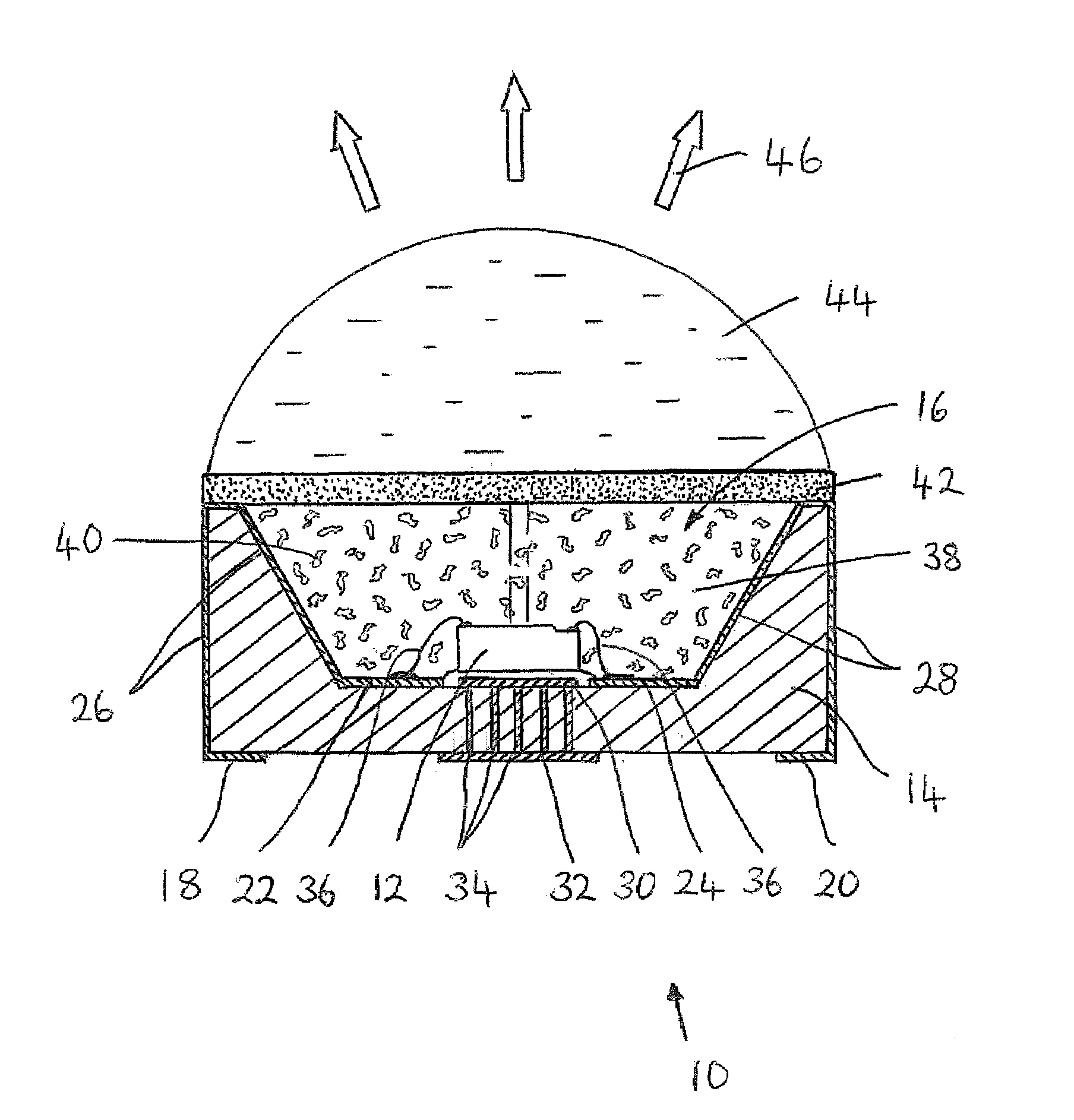
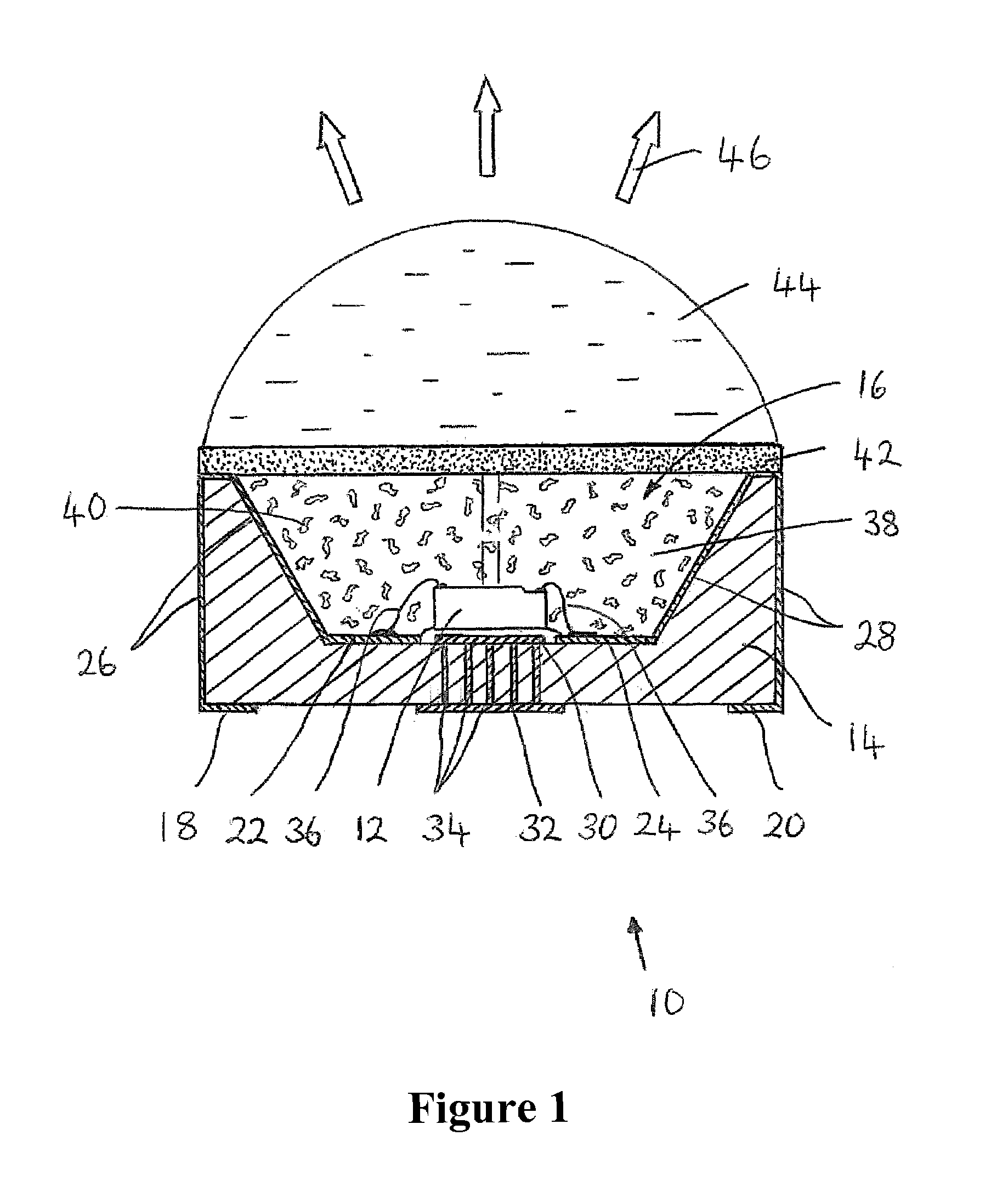
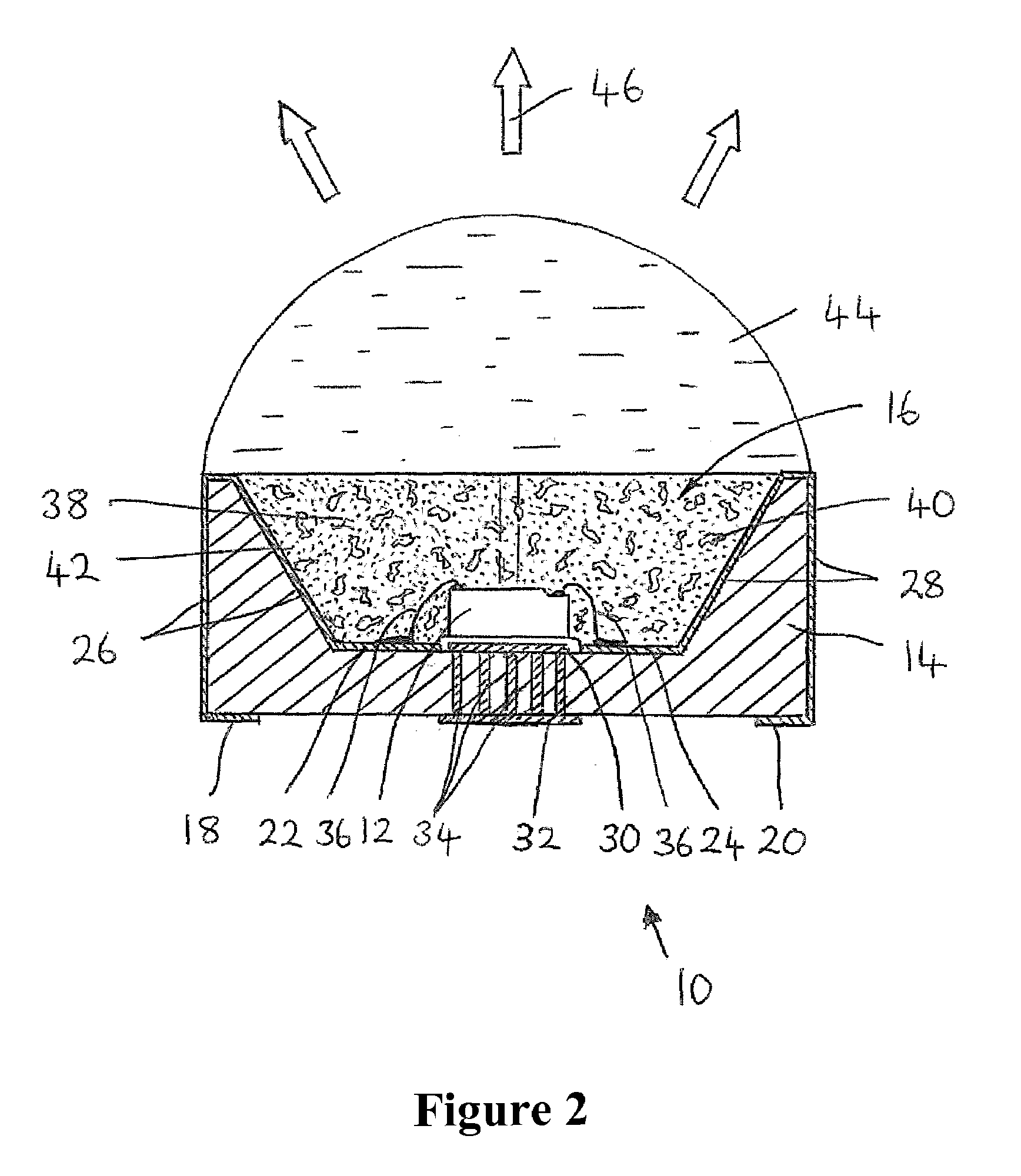
[0027]Embodiments of the invention are directed to light emitting devices, in particular those based on light emitting diodes (LEDs), in which at least the light emitting surface of the LED is coated (covered) with a light transmissive (transparent) medium containing particles of a thermally conducting material distributed throughout its volume. The phosphor (photo-luminescent) material used to achieve a selected color of emitted light can be provided on a surface of the transparent encapsulation, dispersed together with the thermally conducting material within the transparent encapsulation material or provided on the surface of, or incorporated within, an optical component such as a lens that is used to focus or otherwise direct light emitted by the device. The transparent, thermally conducting, encapsulation provides a conduction path for the flow of heat away from the light emitting surface of the LED. In contrast to known LEDs that incorporate a small surface area of phosphor, t...


PUM


Abstract

A light emitting device comprises: an excitation source (LED) operable to generate excitation light of a first wavelength range and a phosphor (photo-luminescent) material configured to absorb at least a part of the excitation radiation and to emit light of a second wavelength range. Light emitted by the device comprises the combined light of the first and second wavelength ranges. The device is characterized by at least the light emitting surface of the excitation source being coated (encapsulated) with an encapsulating material which is transparent to light of the first and second wavelength ranges and which incorporates particles of a thermally conducting material (thermal conductivity ≧100 Wm−1K−1, e.g. silver, aluminum or carbon nano-particles) distributed throughout its volume. The phosphor material can be provided on a surface of the encapsulating material, incorporated in the encapsulating material and / or applied to the surface of, or incorporated, in an optical component such as a lens.

Description

CLAIM OF PRIORITY[0001]This application claims the benefit of priority to U.S. provisional application No. 61 / 021,675 filed Jan. 17, 2008, the specification and drawings of which are incorporated herein by reference.BACKGROUND OF THE INVENTION[0002]1. Field of the Invention[0003]This invention relates to a light emitting device with phosphor wavelength conversion and in particular to a light emitting diode based device with phosphor, photo-luminescent, wavelength conversion to generate a desired color and / or color temperature of light.[0004]2. Description of the Related Art[0005]The development of solid state semiconductor devices, in particular light emitting diodes (LEDs), has opened up the possibility of a new generation of energy efficient lighting solutions. It was not until LEDs emitting in the blue / ultraviolet part of the electromagnetic spectrum were developed that it became practical to develop white light sources based on LEDs (“white LEDs”).[0006]It is predicted that whit...

Claims


Application Information

Patent Timeline
Patent Type & Authority Applications(United States)
IPC IPC(8): F21V9/16
CPCH01L33/507H01L33/56H01L33/644F21V29/006H01L2224/48091H01L2224/73265H01L2224/49107H01L2924/00014F21V29/70
Inventor LI, YI-QUN
Owner INTEMATIX
Why Eureka
Try Eureka