
Photoluminescence color wheels

a color wheel and photoluminescence technology, applied in the field of color wheels, can solve the problems of high cost, relative short operating light expectancy (approximately 4000 to 6000 hours), etc., and achieve the effect of increasing the area of photoluminescence materials

Inactive Publication Date: 2012-08-09
INTEMATIX
View PDF4 Cites 118 Cited by
  • Summary
  • Abstract
  • Description
  • Claims
  • Application Information

AI Technical Summary

Benefits of technology

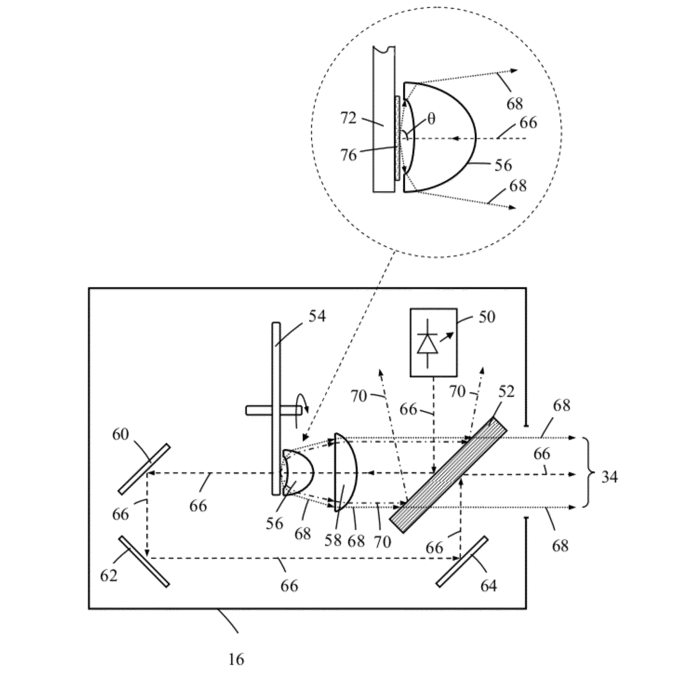
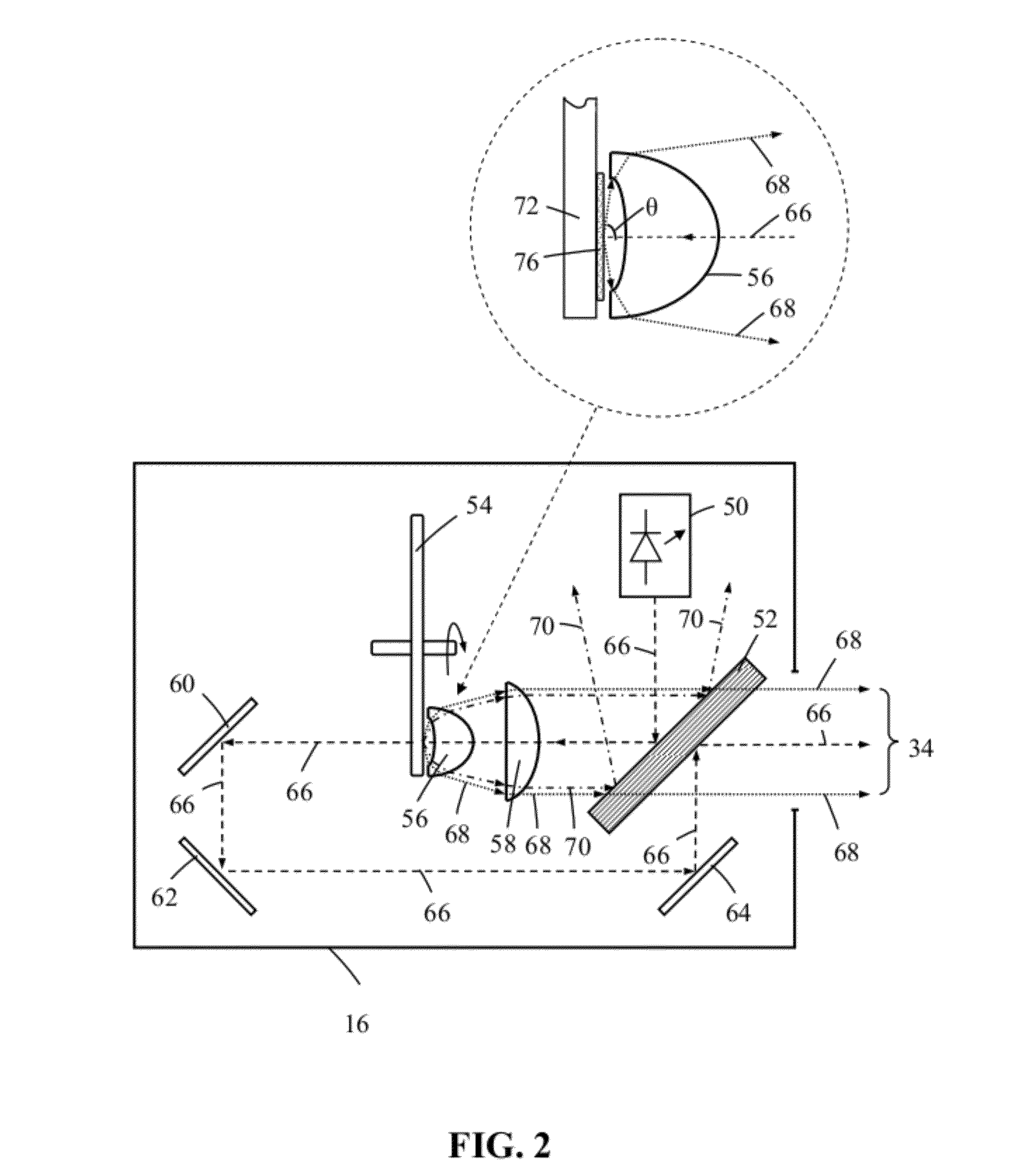
[0016]Where the phosphor materials are blue light excitable the color wheel advantageously comprises regions of phosphor materials that are operable to respectively generate red (620 nm to 750 nm) and green (495 nm to 570 nm) light. Additionally the color wheel can further comprise regions of phosphor materials that are operable to generate a secondary light color such as yellow (570 nm to 590 nm), cyan (blue and green) or magenta (blue and red). Conveniently yellow light can be generated directly using a yellow light emitting photoluminescence material whilst cyan and magenta can be respectively generated using green and red light emitting photoluminescence materials in combination with a proportion of the blue excitation light. Alternatively cyan and magenta light can be generated by sequentially combining green and blue and red and blue light. In one arrangement the disc can further comprise at least one through hole corresponding to a region of the wheel that is used for generating blue light. Such a through hole allows the periodic passage of blue light through the wheel and ensures that blue light travels along a different optical path to that of light generated by the regions of photoluminescence materials. In other arrangements regions of the color wheel that are intended to generate blue light can comprise one or more light reflective regions for selectively reflecting the blue excitation light. Preferably such regions further comprise a light scattering material such as particles of titanium dioxide, barium sulfate, magnesium oxide, silicon dioxide, aluminum oxide or mixtures thereof. Such light scattering materials can simplify the capture of light emitted from the wheel by ensuring that the emission pattern of the blue excitation light from such regions more closely resembles the emission pattern of light from regions including a photoluminescence material(s). Preferably particles of the light scattering material are combined with a light transmissive binder and deposited as a uniform thickness layer on the face of the wheel using the same process (preferably screen printing) used to deposit the photoluminescence material region(s).
[0018]To maximize light emission from the color wheel, the light reflective face of the disc has as high a reflectivity as possible and preferably has a reflectivity of at least 0.90, more preferably at least 0.95 and advantageously at least 0.98. The disc can be fabricated from a material that is intrinsically light reflective though it can alternatively comprise a disc whose surface is treated or coated to make it light reflective. To aid in the dissipation of heat and to reduce possible thermal degradation of the photoluminescence material(s) the disc is advantageously additionally thermally conductive. Advantageously the disc is fabricated from a material with as high a thermal conductivity κ as possible and preferably has a thermal conductivity of at least 150 Wm−1K−1 and more preferably at least 200 W·m−1·K−1. Typically the disc can comprise a metal or a metal alloy such as aluminum (κ≈250 W·m−1·K−1), an alloy of aluminum, an alloy of magnesium or copper (κ≈400 W·m−1·K−1). Alternatively the disc can comprise a polymer material loaded with thermally conductive particles such as for example graphite or a thermally conductive ceramic material such as for example aluminum silicon carbide (AlSiC).
[0021]To increase the area of photoluminescence material that is presented to the excitation light while minimizing the projected area of photoluminescence material the photoluminescence material can comprise surface features that extend from a surface of the photoluminescence material. Such surface features can be provided by overprinting or otherwise depositing a pattern of photoluminescence material features on the region of photoluminescence region(s).

Problems solved by technology

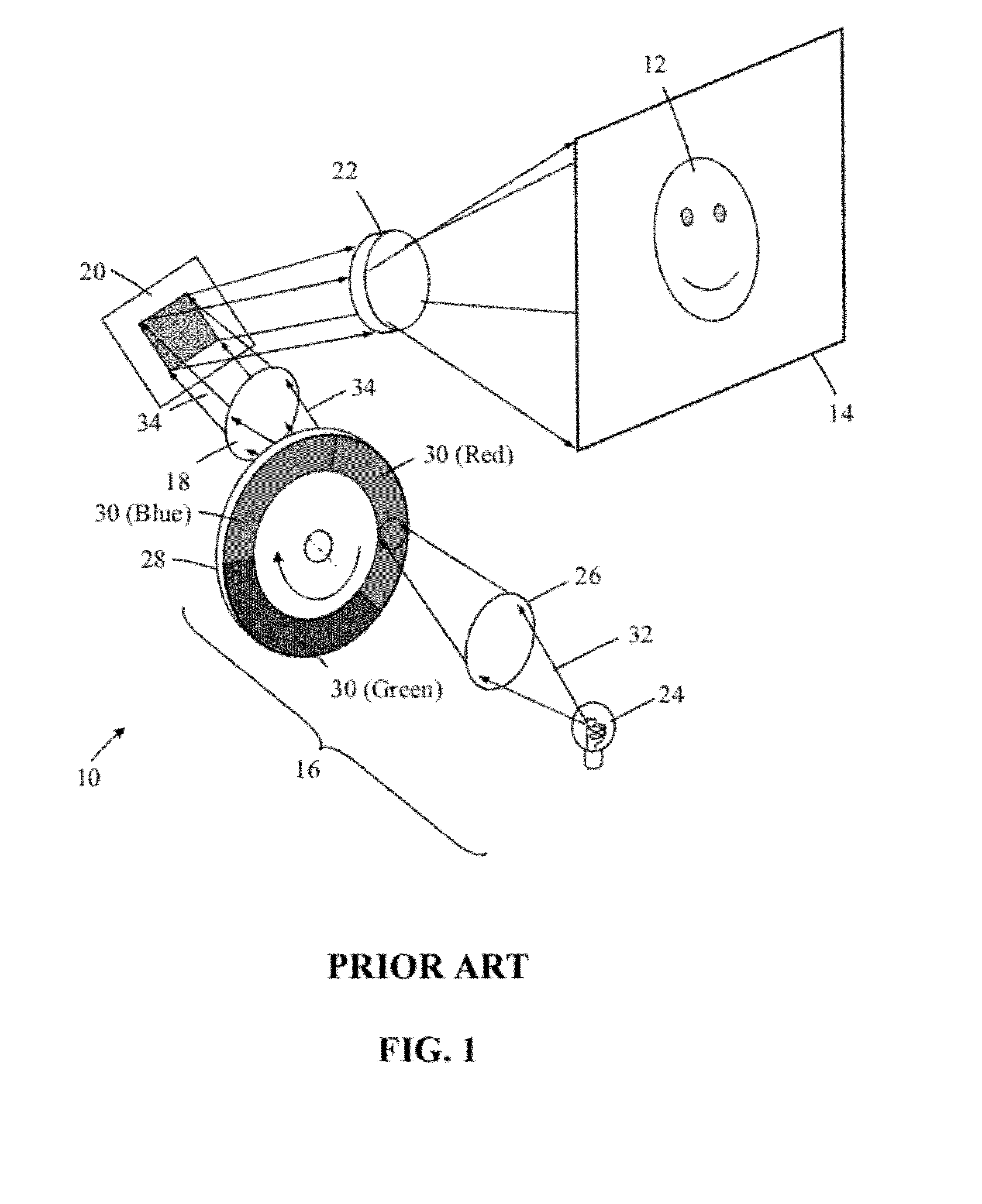
A problem with DLP projection systems that use a color wheel can be the high intensity lamp 24 which can be easily damaged by vibration, needs cooling, has a relatively short operating light expectancy (approximately 4000 to 6000 hours) and is expensive (typically US$200 or more) to replace.

Method used


Image

  • Photoluminescence color wheels
  • Photoluminescence color wheels
  • Photoluminescence color wheels

Examples


Embodiment Construction

[0051]Throughout this patent specification like reference numerals are used to denote like parts. For the purposes of illustration only, the following description is made with reference to photoluminescence material embodied specifically as phosphor materials. However, the invention is applicable to any type of photoluminescence material, such as phosphor materials and quantum dots. A quantum dot is a portion of matter (e.g. semiconductor) whose excitons are confined in all three spatial dimensions that may be excited by radiation energy to emit light of a particular wavelength or range of wavelengths. As such, the invention is not limited to phosphor based wavelength conversion components unless claimed as such.

[0052]A color modulated light source 16 for a digital projection system in accordance with an embodiment of the invention is now described with reference to FIG. 2. As shown in FIG. 3 the light source 16 is operable to generate a color modulated emission product 34 comprisin...


PUM


Abstract

A color wheel comprises: a rotatable disc having a light reflective face and a region of photoluminescence material deposited on the light reflective face. The region of photoluminescence material comprises a substantially uniform thickness layer of a mixture of particles of the photoluminescence material that is deposited on the light reflective face of the disc by screen printing. The photoluminescence materials can comprise blue light or UV excitable photoluminescence materials such as phosphor materials or quantum dots. Color modulated light sources and a method of manufacturing a color wheel are also disclosed.

Description

CROSS-REFERENCE TO RELATED APPLICATION[0001]This application claims the benefit of priority to U.S. Provisional Application No. 61 / 440,233, filed Feb. 7, 2011, entitled “Digital Projection Systems” the specification and drawings of which are incorporated herein by reference in their entirety.BACKGROUND OF THE INVENTION[0002]1. Field of the Invention[0003]This invention relates to color wheels that incorporate photoluminescence materials, such as color wheels that are used to implement digital projection systems or entertainment lighting.[0004]2. Description of the Related Art[0005]There are many types of light generating systems that can be used to implement digital projection and other forms of entertainment lighting products. For example, in a DLP™ (Digital Light Processing—DLP is a trademark of Texas Instruments) digital projection system, color images are generated using a semiconductor chip having an array of microscopic mirrors known as a Digital Micro-mirror Device (DMD) in w...

Claims


Application Information

Patent Timeline
Patent Type & Authority Applications(United States)
IPC IPC(8): F21V9/00G02B5/22F21V9/40F21Y101/00
CPCG02B26/008H04N9/3161H04N9/3114G03B21/204
Inventor YUAN, XIANGLONGDAI, BINGLAU, TSUN YINCOLLIER, IAN
Owner INTEMATIX
Learn More